C8051F380DK Silicon Laboratories Inc, C8051F380DK Datasheet
C8051F380DK
Specifications of C8051F380DK


Related parts for C8051F380DK

C8051F380DK Summary of contents
Page 1
C8051F38x USB MCU www.silabs.com ...
Page 2
Agenda The C8051F38x family C8051F38x advantages C8051F38x enhancements Firmware portability 2 ...
Page 3
C8051F38x Family Features High speed pipelined 8051 MCU core 48 MIPS operation 64K flash and 4K RAM Flexible clocking Internal oscillator with ±0.25% accuracy supports all USB and UART modes Low frequency ...
Page 4
C8051F38x Product Family 12 new USB flash-based devices Ordering Part Number C8051F380-GQ C8051F381-GQ C8051F381-GM C8051F382-GQ C8051F383-GQ C8051F383-GM C8051F384-GQ C8051F385-GQ C8051F385-GM C8051F386-GQ MIPS (Peak) 48 Flash or EPROM Code Memory (Bytes) 64k RAM (Bytes) 4352 Calibrated Internal 48 MHz Oscillator ...
Page 5
C8051F38x USB Advantages Hardware implementation made simple with high functional density Oscillators, resistors, voltage supply regulators and in system programmable memory are integrated on chip All that is recommended are the USB ESD protection diodes VBUS D+ ...
Page 6
C8051F38x Family Enhancements ( Internal oscillator calibrated to 48 MHz Multiplier PLL not required • Multiplier SFR registers remain for backward compatibility with existing code base More communications interfaces Adds second SMBus peripheral • ...
Page 7
C8051F38x Family Enhancements ( Low power optimization Voltage regulators can be disabled or placed into a low power state while maintaining voltage output Pre-fetch engine can be disabled in the standby state to reduce power ...
Page 8
Firmware Porting Considerations ( Firmware functionality between the existing C8051F34x family and the C8051F38x family remains unchanged in the default state All SFR mappings and functionality remain compatible SFRs for removed peripherals remain, such as ...
Page 9
Firmware Porting Considerations ( New firmware can utilize new features of the C8051F38x family Increase ADC sensitivity using lower reference voltage Multiplier initialization no longer needed Can place regulators in low power modes ...
Page 10
C8051F38x Clocking www.silabs.com ...
Page 11
Clocking Options Clock sources Flexible internal oscillator • Default clock after reset • Factory calibrated to 48 MHz Low frequency oscillator at 80 KHz External oscillator • Supports CMOS oscillators, crystals, RC networks and capacitors ...
Page 12
USB Clock USB Clock multiplier is not required since the internal oscillator is calibrated to 48 MHz CLKMUL register still exists for backward compatibility with other USB MCUs 12 Is now the 48 MHz high frequency oscillator Legacy ...
Page 13
The USB Peripheral www.silabs.com ...
Page 14
USB Controller Complete Full/Low speed USB 2.0 compliant function controller Device only, cannot be a host Endpoints Integrated transceiver with clock recovery and configurable pull-up resistors FIFO for Endpoint data ...
Page 15
USB Register Access Scheme Two SFRs used to provide access to the configuration registers (USB0ADR and USB0DAT) First set USB0ADR to define the USB register to access Write/Read data to/from USB0DAT Endpoint Access via the Index ...
Page 16
Indirect Addressing Flow Chart Indirect register access Poll for BUSY USB0ADR Bit 7 = ‘0’ USBAD R Y already set? N Load Target USB0 register into USBADR Write Data to USB0DAT Indirect Write Data Flow 16 USBAD Poll for ...
Page 17
USB0 FIFO Allocation 1024 Bytes of FIFO available to the USB endpoints allocated in XRAM space Endpoints 1-3 can be configured as IN, OUT or split mode with both IN and OUT endpoints Split mode halves the ...
Page 18
C8051 Interrupt Vectors Single interrupt vector for all USB events 11 Interrupt sources can trigger an interrupt event ISR needs to be parsed to determine which interrupt is pending 18 ...
Page 19
Serial Interface Engine (SIE) Serial Interface Engine (SIE) handles data communications to the host in hardware Handles the handshake between the endpoint and the host device Generates an interrupt when valid data packets received Will not ...
Page 20
Control Transfer to Endpoint 0 Setup packet to Endpoint 0: Both IN and OUT directions Used when sending the USB Standard Requests CRC OK 8 data bytes transferred ACK transmitted N Do nothing Discard Data 20 Host ...
Page 21
IN Packet to Endpoint 0 Host is requesting data Data phase of control transfers Used when sending data for the USB standard requests N No response Discard Data N Send NAK INPRDY - IN Packet Ready 21 ...
Page 22
OUT Packet to Endpoint 0 Host is sending data Data phase of control transfers Used when receiving data for standard requests N No response Discard Data SIE controlled Firmware control 22 Host sends out Packet Packet Valid? ...
Page 23
The SMBus/I www.silabs.com C Peripheral 2 ...
Page 24
SMBus/I C Peripheral 2 Master/Slave byte-wise serial data transfers (can switch on-the-fly) Clock signal generation on SCL (Master Mode only) and SDA data synchronization Timeout/bus error recognition, as defined by the SMB0CF configuration register START/STOP timing, ...
Page 25
SMBus Transfer Modes The SMBus interface may be configured to operate as Master and/or a Slave At any particular time, it will be operating in one of the following four modes: Master transmitter (write operation) Master ...
Page 26
SMBus Timing Control The SMBCS1–0 bits in SMB0CF select the SMBus clock source Overflows from Timer 0, Timer 1 or Timer 2 set the time-base Used only when operating as a Master or when the Bus Free ...
Page 27
SMBus Addressing The SMBus hardware has the capability to automatically recognize incoming slave addresses and send an ACK without software intervention SMBus Slave Address register •Programmed device address •Addresses are 7 bits SMBus Slave Address Mask Registers ...
Page 28
SMBus Configuration: SMB0CN Register SMB0CN bits can be used to identify the transfer mode: MASTER TXMODE STA STO All bits combined define the firmware action to take Example: A master data or address ...
Page 29
Acknowledgement Handling Software acknowledgement EHACK bit in register SMB0ADM is cleared to 0 Firmware on the device must detect incoming slave addresses and ACK or NACK the slave address and incoming data bytes. •Receiver—writing the ACK bit ...
Page 30
Write: Master Transmitter Transmit mode always interrupts after the ACK/NAK First byte transfer the device is the master transmitter and interrupts after the ACK The device then continues to be the transmitter and generates the interrupt regardless ...
Page 31
Read: Master Receiver ♦ Transmit mode always interrupts after the ACK/NAK First byte transfer the device is the master transmitter and interrupts after the ACK The device then becomes the receiver and generates the interrupt based on the ...
Page 32
Write: Slave Receiver First byte transfer the device is the slave receiver for the address and direction bit The device continues to be the receiver and generates the interrupt based on the hardware acknowledgement bit (EHACK) •EHACK = ...
Page 33
Read: Slave Transmitter First byte transfer the device is the slave receiver for the address and direction bit EHACK = 1 then interrupts occur after the ACK/NAK EHACK = 0 then interrupts occur before the ACK/NAK period ...
Page 34
SMBus/I C Code Examples 2 ♦ Code examples can be found in the Silicon Labs install directory Silabs\MCU\Examples\C8051F38x Master and slave implementations available ♦ Example initialization routines found in the examples directory 34 ...
Page 35
C8051F38x Enhanced UART www.silabs.com ...
Page 36
Additional UART Module Asynchronous full-duplex serial port Dedicated Baud rate generator Three byte FIFO for receiving characters Baud rates should be less than the system clock divided by 16 Multi-processor mode available Odd, even, ...
Page 37
Operating Modes The UART has several modes of operation, selectable using the SMOD register All modes enable asynchronous communications 8-bit UART TH Extra 9 bit for multi-processor communications Parity can be ...
Page 38
Baud Rate Calculations The baud rate is generated by using the following equation: BaudRate Baud Rate Example: Desired baud rate = 57600 baud Clock input to Timer 1 = System clock = 48 MHz Changing above equation: 38 SYSCLK ...
Page 39
Silicon Labs Tools for USB Development www.silabs.com ...
Page 40
Firmware Examples Installed as part of the Silicon labs IDE and found at http://www.silabs.com/PRODUCTS/MCU/Pages/SoftwareDownloads.aspx Firmware template for HID applications can be used for custom applications USB examples provided (includes host and device software) USB bulk—uses ...
Page 41
USBXpress Allows the developer to implement a USB application without USB expertise Royalty free, Windows certified device driver that can be customized and distributed Microsoft Windows 2000,XP, Vista, 7 and WinCE are supported For use with ...
Page 42
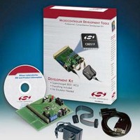
... Wall power adaptor • USB cables and complete documentation TOOLSTICK381DC Enables a quick development and evaluation of the C8051F381 USB MCU Available for $9.90 USD (MSRP) 42 F340 CP2201 C8051F380DK Development Kit The C8051F380DK Development Kit is available for $99.00 USD (MSRP) ...
Page 43
www.silabs.com/USB www.silabs.com ...