ADIS16204BCCZ Analog Devices Inc, ADIS16204BCCZ Datasheet - Page 16
ADIS16204BCCZ
Manufacturer Part Number
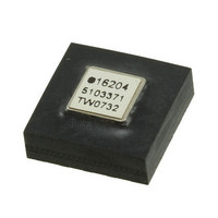
ADIS16204BCCZ
Description
IC ACCEL DIGITAL HI-G 16-LGA
Manufacturer
Analog Devices Inc
Datasheet
1.ADIS16204PCBZ.pdf
(24 pages)
Specifications of ADIS16204BCCZ
Acceleration Range
±37g, 70g
Axis
X, Y
Sensitivity
17.125 LSB/mg, 8.407 LSB/mg
Voltage - Supply
3 V ~ 3.6 V
Output Type
Digital
Bandwidth
400Hz
Interface
SPI
Mounting Type
Surface Mount
Package / Case
16-LGA
No. Of Axes
2
Sensor Case Style
LGA
No. Of Pins
16
Supply Voltage Range
3V To 3.6V
Operating Temperature Range
-40°C To +105°C
Svhc
No SVHC (18-Jun-2010)
Family Name
ADIS16204
Package Type
LGA
Operating Supply Voltage (min)
3V
Operating Supply Voltage (typ)
3.3V
Operating Supply Voltage (max)
3.6V
Operating Temperature (min)
-40C
Operating Temperature (max)
105C
Operating Temperature Classification
Industrial
Product Depth (mm)
8mm
Product Height (mm)
5.2mm
Product Length (mm)
8mm
Mounting
Surface Mount
Pin Count
16
Interface Type
SPI
Sensitivity Per Axis
17.125mg / LSB
Rohs Compliant
Yes
Lead Free Status / RoHS Status
Lead free / RoHS Compliant
For Use With
ADIS16204/PCBZ - BOARD EVAL FOR ADIS16204/PCB
Lead Free Status / Rohs Status
Compliant
Available stocks
Company
Part Number
Manufacturer
Quantity
Price
Company:

Part Number:
ADIS16204BCCZ
Manufacturer:
ST
Quantity:
390


ADIS16204
Table 13. YACCL_SCALE Register Definition
Address
0x17, 0x16
1
2
Table 14. Calibration Register Bit Descriptions
Bit
15:12
11:0
OPERATIONAL CONTROL
Internal Sample Rate
The internal sample rate defines how often data output variables
are updated, independent of the rate at which they are read out
on the SPI port. The SMPL_PRD register controls the ADIS16204
internal sample rate and has two parts: a selectable time base and
a multiplier. The following relationship produces the sample rate:
where:
T
T
N
The default value is the maximum 4096 SPS, and the contents of
this register are nonvolatile.
Table 15. SMPL_PRD Register Definition
Address
0x37, 0x36
Table 16. SMPL_PRD Bit Descriptions
Bit
15:8
7
6:0
Here is an example calculation of the sample period for the
ADIS16204:
The sample rate setting has a direct impact on the SPI data
rate capability. For sample rates ≥1024 SPS, the SPI SCLK can
run at a rate up to 2.5 MHz. For sample rates <1024 SPS, the SPI
SCLK can run at a rate up to 1 MHz.
Scale is the weight of each LSB.
Equates to a scale factor of one.
S
B
S
is the sample period.
is the time base.
is the increment setting.
T
If SMPL_PRD = 0x0007, B7 − B0 = 00000111
B7 = 0 → T
B6…B0 = 000000111 → N
T
f
S
S
S
= 1∕T
Description
Not used
Time base
Multiplier
= T
= T
0 = 122.07 μs, 1 = 3.784 ms
Description
Not used
Data bits
B
B
S
× (N
× (N
= 1024 SPS
Scale
0.0488%
B
Default
0x0001
= 122.07 μs
S
S
+ 1)
+ 1) = 122.07 μs × (7 + 1) = 976.56 μs
1
Default
0x0800
S
= 7
Format
N/A
2
Format
Binary
Access
R/W
Access
R/W
Rev. B | Page 16 of 24
The sample rate setting also affects the power dissipation.
When the sample rate is set below 1024 SPS, the power
dissipation typically reduces by a factor of 68%. The two
different modes of operation offer a system-level trade-off
between performance (sample rate, serial transfer rate) and
power dissipation.
Power Management
In addition to offering two different performance modes for
power optimization, the ADIS16204 offers a programmable
shutdown period. Writing the appropriate sleep time to the
SLP_CNT register shuts the device down for the specified
time. The following example provides an illustration of this
relationship:
After completing the sleep period, the ADIS16204 returns to
normal operation.
Table 17. SLP_CNT Register Definition
Address
0x3B, 0x3A
1
Table 18. SLP_CNT Bit Descriptions
Bit
15:8
7:0
Auxiliary DAC
The auxiliary DAC provides a 12-bit level adjustment function.
The AUX_DAC register controls the operation of this feature.
It offers a rail-to-rail buffered output that has a range of 0 V to
2.5 V. The DAC can drive its output to within 5 mV of the
ground reference when it is not sinking current. As the output
approaches ground, the linearity begins to degrade (100 LSB
beginning point). As the sink current increases, the nonlinear
range increases. The DAC output latch function, contained in
the COMMAND register, provides continuous operation while
writing to each byte of this register. The contents of this register
are volatile, which means that the desired output level must be
set after every reset and power cycle event.
Table 19. AUX_DAC Register Definition
Address
0x31, 0x30
1
Table 20. AUX_DAC Bit Descriptions
Bit
15:12
11:0
the 2.5 V range out of output voltage.
Scale is the weight of each LSB.
Scale is the weight of each LSB. In this case, it represents 4095 codes over
B7 … B0 = 00000110
Sleep period = 3 seconds
Description
Not used
Data bits
Description
Not used
Data bits
Scale
0.6105 mV
Scale
0.5 sec
1
1
Default
0x0000
Default
0x0000
Format
Binary
Format
Binary
Access
W only
Access
R/W
Related parts for ADIS16204BCCZ
Image
Part Number
Description
Manufacturer
Datasheet
Request
R

Part Number:
Description:
±1.7g Dual-Axis IMEMS Accelerometer Evaluation Board
Manufacturer:
Analog Devices Inc
Datasheet:

Part Number:
Description:
Inertial Sensor Evaluation System
Manufacturer:
Analog Devices Inc
Datasheet:
Part Number:
Description:
Manufacturer:
Analog Devices Inc
Datasheet:
Part Number:
Description:
Manufacturer:
Analog Devices Inc
Datasheet:
Part Number:
Description:
Manufacturer:
Analog Devices Inc
Datasheet:
Part Number:
Description:
Manufacturer:
Analog Devices Inc
Datasheet:
Part Number:
Description:
Manufacturer:
Analog Devices Inc
Datasheet:
Part Number:
Description:
Manufacturer:
Analog Devices Inc
Datasheet:
Part Number:
Description:
Manufacturer:
Analog Devices Inc
Datasheet:
Part Number:
Description:
Manufacturer:
Analog Devices Inc
Datasheet:
Part Number:
Description:
Manufacturer:
Analog Devices Inc
Datasheet:
Part Number:
Description:
Manufacturer:
Analog Devices Inc
Datasheet:
Part Number:
Description:
Manufacturer:
Analog Devices Inc
Datasheet: