SPMB250-A1 STMicroelectronics, SPMB250-A1 Datasheet - Page 9
SPMB250-A1
Manufacturer Part Number
SPMB250-A1
Description
ACCELEROMETER 3-AXIS 2G 6G MOD
Manufacturer
STMicroelectronics
Series
MOTIONBEE™r
Datasheet
1.SPMB250-A1.pdf
(18 pages)
Specifications of SPMB250-A1
Axis
X, Y, Z
Acceleration Range
±2g, 6g
Sensitivity
1024LSB/g, 340LSB/g
Voltage - Supply
3.6 V ~ 6 V
Output Type
Analog
Mounting Type
Surface Mount
Package / Case
Module
Lead Free Status / RoHS Status
Lead free / RoHS Compliant
Bandwidth
-
Interface
-
Other names
497-9085


SPMB250-A1
6.4
6.5
Pad description
When used on a motherboard the boundary pads on the SPMB250-A1 can be used to get
the connections with the remaining part of the circuit present on the motherboard itself.
The meaning of the pads is listed in the following table:
Table 4.
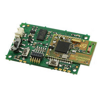
LED indicators
Two LED L2 (Led2) and L3 (Led3) are connected to the GPIO of SPZB250 module to be
used to monitor the module activity. Driving pin of L3 is also available as pad out (P10).
P10
P1
P2
P3
P4
P5
P6
P7
P8
P9
N.
J1 – Vcc- (GND)
SW1 (RESET /
L3 – GPIO13
Pad description
J1 – Vcc +
Pin name
SW2-O
RSTB)
GPIO8
SW2-I
GND
GND
SW3
Power GND input voltage supply
Power Positive input voltage supply
Power Power switch pole connected to the circuit
Power Power switch pole connected to Vin +
Power
Power
Doc ID 15179 Rev 2
I/O
I/O
O
I
I
Reset push button. Reset occurs when this pad is tied to
GND
GPIO8 of SPZB250 module
General purpose push button / commissioning push button.
It can used also as I/O pin
Led 3 general purpose (connected to SPZB250 GPIUO13) A
resistor is needed to limit the current
Description
Board description
9/18
Related parts for SPMB250-A1
Image
Part Number
Description
Manufacturer
Datasheet
Request
R

Part Number:
Description:
Zigbee / 802.15.4 Modules & Development Tools Wireless Sensor Kit 802.15.4 Transceiver
Manufacturer:
STMicroelectronics
Datasheet:

Part Number:
Description:
STMicroelectronics [RIPPLE-CARRY BINARY COUNTER/DIVIDERS]
Manufacturer:
STMicroelectronics
Datasheet:
Part Number:
Description:
STMicroelectronics [LIQUID-CRYSTAL DISPLAY DRIVERS]
Manufacturer:
STMicroelectronics
Datasheet:

Part Number:
Description:
BOARD EVAL FOR MEMS SENSORS
Manufacturer:
STMicroelectronics
Datasheet:
Part Number:
Description:
NPN TRANSISTOR POWER MODULE
Manufacturer:
STMicroelectronics
Datasheet:
Part Number:
Description:
TURBOSWITCH ULTRA-FAST HIGH VOLTAGE DIODE
Manufacturer:
STMicroelectronics
Datasheet:
Part Number:
Description:
Manufacturer:
STMicroelectronics
Datasheet:
Part Number:
Description:
DIODE / SCR MODULE
Manufacturer:
STMicroelectronics
Datasheet:
Part Number:
Description:
DIODE / SCR MODULE
Manufacturer:
STMicroelectronics
Datasheet:
Part Number:
Description:
Search -----> STE16N100
Manufacturer:
STMicroelectronics
Datasheet:
Part Number:
Description:
Search ---> STE53NA50
Manufacturer:
STMicroelectronics
Datasheet:
Part Number:
Description:
NPN Transistor Power Module
Manufacturer:
STMicroelectronics
Datasheet: