102.1947 FISCHER CONNECTORS, 102.1947 Datasheet - Page 70
102.1947
Manufacturer Part Number
102.1947
Description
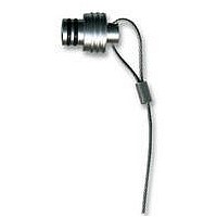
SEALING CAP, MATING FACE OF RECEPTACLE
Manufacturer
FISCHER CONNECTORS
Datasheet
1.102.1947.pdf
(108 pages)
Specifications of 102.1947
Accessory Type
Sealing Cap
Rohs Compliant
Yes
For Use With
Mating Face Of The Receptacles
Lead Free Status / RoHS Status
Lead free / RoHS Compliant


L
Operating Voltages (Rated Voltage)
The test voltages (dielectric withstanding voltage) listed under «Electrical Specifications» are readings measured in our
laboratory according to IEC 60512-2, test 4a (Voltage proof). This standard is equivalent to the German DIN 41 640, section 8 as
well as to US standards MIL-STD-202, method 301 and MIL-STD-1344, method 3001.
The test results can also be related to the British Standard BS 9520, paragraph 1.2.4.5 (Voltage proof).
All tests are carried out under standard temperature and pressure. All other conditions require the appropriate derating factors
in conformance to the applicable standards.
If no other restrictive standards or local environmental regulations are to be applied, we recommend the calculation of the rated
voltages according to IEC 60130-1, also specified in BS 9520, paragraph 1.1.12.3 (c). For connectors up to 1 kV rated voltage, this
method of calculation also corresponds to the recommendation of MIL-STD-1344, method 3001.
Connectors for rated voltages up to and including 1 kV:
Connectors for rated voltages higher than 1 kV:
IEC 60512 : Standard of the International Electrotechnical Commission:
IEC 60130 : Includes connectors for frequencies below 3 MHz.
BS 9520
Current Rating (Maximum admissible current)
The current-carrying capacities, listed under «Electrical Specifications» were calculated in our test laboratory according to IEC
60512-3, test 5a (Temperature rise) and 5b (Current - temperature derating), equivalent to DIN 41 640, sections 11 and 3.
The preferred values in these standards are 20°C, 30°C and 40°C temperature rise above the ambient temperature. While cable
manufacturers specify the maximum admissible current at 20°C, some manufacturers of connectors specify the values at 40 °C
temperature rise. We list both values in our catalogue.
When selecting a connector, attention must be paid to the fact that the temperature rise caused by current must be added to
the ambient temperature and that the resulting value may not exceed the upper component limit, listed under «Operating
Temperatures» on page L8.
In the picture below, the corrected derating curve shows that the current must approach zero when the upper component
temperature limit has been reached.
The values of the maximum admissible current, listed under «Electrical Specifications», are valid for each contact, wired with
the largest possible conductor cross-section. For coaxial and triaxial connectors, the current is valid for the center and the outer
contact.
Depending on the conductor cross-section, single contacts can carry a higher current if remaining contacts carry corres-
pondingly lesser loads. As general guideline a single contact can carry twice the current value indicated in our tables.
Due to the measuring method, cable heating has a considerable influence on the connector current capacity.
Please contact us if you require more detailed information.
For voltage and current ratings of right angle plugs «WS, WSE, WSO» and bulkhead feedthroughs «WDE», please
consult us.
Operating voltage =
Operating voltage =
: British Standard Specification for Electrical connectors of assessed quality for d.c. and low frequency application.
«Electromechanical components for electronic equipment»
Current carrying capacity
Permissible operating
Current capacity (derating curve)
Upper current limit
(set by the chosen
temperature rise)
Test voltage
Test voltage
range
1.5
3
TECHNICAL INFORMATION
Base curve
with minimum test voltage of 500 V
with minimum test voltage of 3 kV
Corrected curve
9
Upper component
temperature limit
Ambient temperature