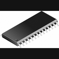
CS8415A-CS Cirrus Logic Inc, CS8415A-CS Datasheet - Page 3

CS8415A-CS
Manufacturer Part Number
CS8415A-CS
Description
IC, DIGITAL AUDIO RECEIVER, SOIC-28
Manufacturer
Cirrus Logic Inc
Specifications of CS8415A-CS
Audio Control Type
Digital
Control Interface
I2C, Serial
Control / Process Application
AV & DVD Receivers, CD-R, Digital Mixing Consoles
Supply Voltage Range
2.85V To 5.5V
Lead Free Status / RoHS Status
Contains lead / RoHS non-compliant
Available stocks
Company
Part Number
Manufacturer
Quantity
Price
Part Number:
CS8415A-CS
Manufacturer:
CIRRUS
Quantity:
20 000
Company:
Part Number:
CS8415A-CSR
Manufacturer:
CirrusLogic
Quantity:
569
Company:
Part Number:
CS8415A-CSZ
Manufacturer:
CIRRUS
Quantity:
108
Part Number:
CS8415A-CSZ
Manufacturer:
CRYSTAL
Quantity:
20 000
LIST OF FIGURES
LIST OF TABLES
DS470PP3
9. PIN DESCRIPTION - SOFTWARE MODE ............................................................................. 30
10. HARDWARE MODE ............................................................................................................. 32
11. PIN DESCRIPTION - HARDWARE MODE .......................................................................... 33
12. APPLICATIONS .................................................................................................................. 35
13. PACKAGE DIMENSIONS ................................................................................................... 36
14. APPENDIX A: EXTERNAL AES3/SPDIF/IEC60958 RECEIVER COMPONENTS ............. 38
15. APPENDIX B: CHANNEL STATUS AND USER DATA BUFFER MANAGEMENT ........... 40
Figure 1. Audio Port Master Mode Timing ...................................................................................... 6
Figure 2. Audio Port Slave Mode and Data Input Timing................................................................ 6
Figure 3. SPI Mode Timing ............................................................................................................. 7
Figure 4. Two-Wire Mode timing ..................................................................................................... 8
Figure 5. Recommended Connection Diagram for Software Mode ................................................ 9
Figure 6. Serial Audio Output Example Formats........................................................................... 12
Figure 7. Jitter Attenuation Characteristics of PLL with 8-96 kHz Fs Filter Components.............. 14
Figure 8. Jitter Attenuation Characteristics of PLL with 32-96 kHz Fs Filter Components............ 14
Figure 9. AES3 Receiver Timing for C & U pin output data .......................................................... 16
Figure 10. Control Port Timing in SPI Mode ................................................................................. 17
Figure 11. Hardware Mode ........................................................................................................... 18
Figure 12. Control Port Timing in Two-Wire Mode........................................................................ 19
Figure 12. Professional Input Circuit ............................................................................................. 38
Figure 13. Transformerless Professional Input Circuit .................................................................. 38
Figure 14. Consumer Input Circuit ................................................................................................ 39
Figure 15. S/PDIF MUX Input Circuit ............................................................................................ 39
Figure 16. TTL/CMOS Input Circuit............................................................................................... 39
Figure 17. Channel Status Data Buffer Structure.......................................................................... 40
Figure 18. Flowchart for Reading the E Buffer.............................................................................. 40
Table 1. PLL External Component Values .................................................................................... 14
Table 2. Control Register Map Summary...................................................................................... 20
Table 3. Equivalent Software Mode Bit Definitions ....................................................................... 32
Table 4. Hardware Mode Start-up Options ................................................................................... 32
8.13 Receiver Error Mask (11h) ............................................................................................. 28
8.14 Channel Status Data Buffer Control (12h) ...................................................................... 28
8.15 User Data Buffer Control (13h) ....................................................................................... 29
8.16 Q-Channel Subcode Bytes 0 to 9 (14h - 1Dh) (Read Only) ........................................... 29
8.17 OMCK/RMCK Ratio (1Eh) (Read Only).......................................................................... 29
8.18 C-bit or U-bit Data Buffer (1Fh - 37h) ............................................................................. 29
8.19 CS8415A I.D. and Version Register (7Fh) (Read Only) ................................................. 29
10.1 Serial Audio Port Formats ............................................................................................. 32
12.1 Reset, Power Down and Start-up .................................................................................. 35
12.2 ID Code and Revision Code .......................................................................................... 35
12.3 Power Supply, Grounding, and PCB layout ................................................................... 35
14.1 AES3 Receiver External Components ........................................................................... 38
14.2 Isolating Transformer Requirements ............................................................................. 38
15.1 AES3 Channel Status (C) Bit Management ................................................................... 40
15.2 Accessing the E buffer ................................................................................................... 40
15.3 AES3 User (U) Bit Management .................................................................................... 41
15.2.1 Reserving the first 5 bytes in the E buffer ......................................................... 40
15.2.2 Serial Copy Management System (SCMS) ....................................................... 41
15.2.3 Channel Status Data E Buffer Access .............................................................. 41
CS8415A
3


