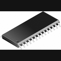
CS8415A-CS Cirrus Logic Inc, CS8415A-CS Datasheet - Page 24

CS8415A-CS
Manufacturer Part Number
CS8415A-CS
Description
IC, DIGITAL AUDIO RECEIVER, SOIC-28
Manufacturer
Cirrus Logic Inc
Specifications of CS8415A-CS
Audio Control Type
Digital
Control Interface
I2C, Serial
Control / Process Application
AV & DVD Receivers, CD-R, Digital Mixing Consoles
Supply Voltage Range
2.85V To 5.5V
Lead Free Status / RoHS Status
Contains lead / RoHS non-compliant
Available stocks
Company
Part Number
Manufacturer
Quantity
Price
Part Number:
CS8415A-CS
Manufacturer:
CIRRUS
Quantity:
20 000
Company:
Part Number:
CS8415A-CSR
Manufacturer:
CirrusLogic
Quantity:
569
Company:
Part Number:
CS8415A-CSZ
Manufacturer:
CIRRUS
Quantity:
108
Part Number:
CS8415A-CSZ
Manufacturer:
CRYSTAL
Quantity:
20 000
24
8.6
8.7
8.8
8.9
7
7
7
7
0
0
0
0
0
Interrupt 2 Status (08h) (Read Only)
For all bits in this register, a “1” means the associated interrupt condition has occurred at least once since
the register was last read. A ”0” means the associated interrupt condition has NOT occurred since the last
reading of the register. Reading the register resets all bits to 0, unless the interrupt mode is set to level and
the interrupt source is still true. Status bits that are masked off in the associated mask register will always
be “0” in this register. This register defaults to 00h.
DETU - D to E U-buffer transfer interrupt.
Indicates the completion of a D to E U-buffer transfer. See “Channel Status and User Data Buffer Manage-
ment” on page 38 for more information.
QCH - A new block of Q-subcode data is available for reading.
The data must be completely read within 588 AES3 frames after the interrupt occurs to avoid corruption of
the data by the next block.
Interrupt 1 Mask (09h)
The bits of this register serve as a mask for the Interrupt 1 register. If a mask bit is set to 1, the error is un-
masked, meaning that its occurrence will affect the INT pin and the status register. If a mask bit is set to 0,
the error is masked, meaning that its occurrence will not affect the INT pin or the status register. The bit
positions align with the corresponding bits in Interrupt 1 register. This register defaults to 00h.
Interrupt 1 Mode MSB (0Ah) and Interrupt 1 Mode LSB (0Bh)
The two Interrupt Mode registers form a 2-bit code for each Interrupt Register 1 function. There are three
ways to set the INT pin active in accordance with the interrupt condition. In the Rising edge active mode,
the INT pin becomes active on the arrival of the interrupt condition. In the Falling edge active mode, the INT
pin becomes active on the removal of the interrupt condition. In Level active mode, the INT interrupt pin be-
comes active during the interrupt condition. Be aware that the active level (Actice High or Low) only depends
on the INT[1:0] bits. These registers default to 00.
00 - Rising edge active
01 - Falling edge active
10 - Level active
11 - Reserved
Interrupt 2 Mask (0Ch)
The bits of this register serve as a mask for the Interrupt 2 register. If a mask bit is set to 1, the error is un-
masked, meaning that its occurrence will affect the INT pin and the status register. If a mask bit is set to 0,
the error is masked, meaning that its occurrence will not affect the INT pin or the status register. The bit
positions align with the corresponding bits in Interrupt 2 register. This register defaults to 00h.
OSLIPM
OSLIP1
OSLIP0
6
6
6
0
6
0
5
5
5
0
0
0
0
5
0
4
0
4
0
4
0
0
4
0
DETUM
DETU
3
3
3
0
0
0
3
DETCM
DETC1
DETC0
2
0
2
2
2
0
QCHM
QCH
1
1
1
0
0
0
1
CS8415A
RERRM
RERR1
RERR0
DS470F4
0
0
0
0
0
0


