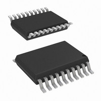
ADUM3470CRSZ Analog Devices Inc, ADUM3470CRSZ Datasheet - Page 27

ADUM3470CRSZ
Manufacturer Part Number
ADUM3470CRSZ
Description
IC, DIGITAL ISOLATOR, 60NS, SSOP-20
Manufacturer
Analog Devices Inc
Series
iCoupler®r
Datasheet
1.EVAL-ADUM3471EBZ.pdf
(32 pages)
Specifications of ADUM3470CRSZ
No. Of Channels
4
Propagation Delay
60ns
Supply Current
33mA
Supply Voltage Range
3V To 3.6V, 4.5V To 5.5V
Digital Ic Case Style
SSOP
No. Of Pins
20
Operating Temperature
-40°C ~ 105°C
Inputs - Side 1/side 2
4/0
Number Of Channels
4
Isolation Rating
2500Vrms
Voltage - Supply
3.3V, 5V
Data Rate
25Mbps
Output Type
Logic
Package / Case
20-SSOP (0.200", 5.30mm Width)
Rohs Compliant
Yes
Lead Free Status / RoHS Status
Lead free / RoHS Compliant
Lead Free Status / RoHS Status
Lead free / RoHS Compliant
Table 18. Transformer Reference Designs
Part No.
JA4631-BL
JA4650-BL
KA4976-AL
TGSAD-260V6LF
TGSAD-290V6LF
TGSAD-292V6LF
TGAD-260NARL
TGAD-290NARL
TGAD-292NARL
TRANSFORMER ISOLATION VOLTAGE
Isolation voltage and isolation type should be determined for
the requirements of the application and then specified. The
transformers in Table 18 have been specified for 2500 V rms
for supplemental or basic isolation and for 1500 V rms functional
isolation. Other isolation levels and isolation voltages can be
specified and requested from the manufacturers in Table 18
or from other manufacturers.
SWITCHING FREQUENCY
The ADuM347x switching frequency can be adjusted from
200 kHz to 1 MHz by changing the value of the R
shown in Figure 38, Figure 39, and Figure 40. The value of the
R
determined from the switching frequency vs. R
curve shown in Figure 9. The output filter inductor value and
output capacitor value for the ADuM347x application schematics
have been designed to be stable over the switching frequency
range from 500 kHz to 1 MHz, when loaded from 10% to 90%
of the maximum load.
The ADuM347x also has an open-loop mode where the output
voltage is not regulated and is dependent on the transformer
turns ratio, N
output load current and the losses in the dc-to-dc converter
circuit. This open-loop mode is selected when the OC pin is
connected high to the V
switching frequency is 318 kHz.
OC
resistor needed for the desired switching frequency can be
S
/N
P
Manufacturer
Coilcraft
Coilcraft
Coilcraft
Halo Electronics
Halo Electronics
Halo Electronics
Halo Electronics
Halo Electronics
Halo Electronics
, and the conditions of the output including
DD2
pin. In open-loop mode, the
1CT:2CT
1CT:3CT
1CT:5CT
Turns Ratio,
PRI:SEC
1CT:2CT
1CT:3CT
1CT:5CT
1CT:2CT
1CT:3CT
1CT:5CT
OC
ADuM3470/ADuM3471/ADuM3472/ADuM3473/ADuM3474
ET Constant
(V × μs Min)
18
18
18
14
14
14
14
14
14
OC
resistance
resistor
Rev. 0 | Page 27 of 32
Total Primary
Inductance (μH)
255
255
255
389
389
389
389
389
389
TRANSIENT RESPONSE
The load transient response of the output voltage of the ADuM347x
for 10% to 90% of the full load is shown in Figure 30 to Figure 33
for the application schematics in Figure 38 and Figure 39. The
response shown is slow but stable and can have more output
change than desired for some applications. The output voltage
change with load transient has been reduced, and the output has
been shown to remain stable by adding more inductance to the
output circuits, as shown in the second V
Figure 30 to Figure 33.
COMPONENT SELECTION
The ADuM347x digital isolators with 2 W dc-to-dc converters
require no external interface circuitry for the logic interfaces. Power
supply bypassing is required at the input and output supply pins.
Note that a low ESR ceramic bypass capacitor of 0.1 μF is required
on Side 1 between Pin 9 and Pin 10, and on Side 2 between Pin 18
and Pin 19, as close to the chip pads as possible.
The power supply section of the ADuM347x uses a high oscillator
frequency to efficiently pass power through the external power
transformer. In addition, normal operation of the data section
of the i Coupler introduces switching transients on the power
supply pins. Bypass capacitors are required for several operating
frequencies. Noise suppression requires a low inductance, high
frequency capacitor; ripple suppression and proper regulation
require a large value capacitor. To suppress noise and reduce ripple,
large-valued ceramic capacitors of X5R or X7R dielectric type are
recommended. The recommended capacitor value is 10 μF for
V
available in moderate 1206 or 1210 sizes for voltages up to 10 V. For
output voltages larger than 10 V, two 22 μF ceramic capacitors can
be used in parallel. See Table 19 for recommended components.
DD1
and 47 μF for V
Total Primary
Resistance (Ω)
0.2
0.2
0.2
0.8
0.8
0.8
0.8
0.8
0.8
ISO
. These capacitors have a low ESR and are
Isolation
Voltage (rms)
2500
2500
2500
2500
2500
2500
1500
1500
1500
Isolation
Type
Basic
Basic
Basic
Supplemental
Supplemental
Supplemental
Functional
Functional
Functional
ISO
output waveform in
Reference
Figure 38
Figure 39
Figure 40
Figure 38
Figure 39
Figure 40
Figure 38
Figure 39
Figure 40


