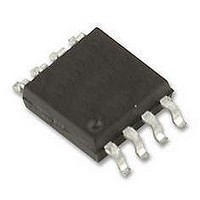
BD3533FVM-TR Rohm Semiconductor, BD3533FVM-TR Datasheet

BD3533FVM-TR
Specifications of BD3533FVM-TR
Related parts for BD3533FVM-TR
BD3533FVM-TR Summary of contents
Page 1
TECHNICAL NOTE High-performance Regulator IC Series for PCs Termination Regulators for DDR-SDRAMs BD3533F/FVM/EKN(1A),BD3531F(1.5A),BD3532F/EFV/KN(3A) Description BD3533/31/ termination regulator compatible with JEDEC DDR-SDRAM, which functions as a linear power supply incorporating an N-channel MOSFET and provides a sink/source current capability ...
Page 2
... Reduced by 8.0mW for each increase 1℃ over 25℃(When mounted on a board 70mm×70mm×1.6mm Glass-epoxyPCB). *5 Reduced by 3.68mW for each increase 1℃ over 25℃(With no heat sink). *6 Reduced by 5.80mW for each increase 1℃ over 25℃(When mounted on a board 70mm×70mm×1.6mm Glass-epoxyPCB). BD3533F BD3533FVM Symbol *1*2 VCC ...
Page 3
OPERATING CONDITIONS ◎BD3533F/FVM/EKN(Ta=25℃) Parameter Input Voltage Termination Input Voltage VDDQ Reference Voltage Enable Input Voltage ◎BD3531F(Ta=25℃) Parameter Input Voltage Termination Input Voltage EN Input Voltage ◎BD3532F/EFV/KN(Ta=25℃) Parameter Input Voltage Termination Input Voltage EN Input Voltage ★ No radiation-resistant design ...
Page 4
CHARACTERISTICS ◎BD3533F/FVM/EKN ELECTRICAL CHARACTERISTICS(unless otherwise noted, Ta=25℃ VCC=3.3V VEN=3V VDDQ=1.8V VTT_IN=1.8V) Parameter [Input of Reference Voltage] Input Impedance ZVDDQ Output Voltage1 Output Voltage2 Output Voltage3 Output Voltage4 [Reference voltage] Source Current Sink Current [UVLO] UVLO OFF Voltage Hysteresis Voltage ...
Page 5
ELECTRICAL CHARACTERISTICS(unless otherwise noted, Ta=25℃ VCC=5V VEN=3V VDDQ=2.5V VTT_IN=2.5V) Parameter Symbol Standby Current IST Bias Current ICC [Enable] Hi Level Enable Input VENHI Voltage Low Level Enable Input VENLOW Voltage Enable Pin Input Current IEN [Termination] Termination Output Voltage ...
Page 6
Data VTT(10mV/Div) ITT(1A/Div) 10μsec/Div Fig.1 DDRⅠ(-1A→1A) BD3531 VTT(10mV/Div) ITT(1A/Div) 10μsec/Div Fig.4 DDRⅠ(1A→-1A) BD3531 VTT(10mV/Div) ITT(1A/Div) 10μsec/Div Fig.7 DDRⅡ(-1A→1A) BD3531 VTT(10mV/Div) ITT(1A/Div) 10μsec/Div Fig.10 DDRⅡ(1A→-1A) BD3531 VTT(10mV/Div) ITT(1A/Div) 10μsec/Div Fig.2 DDRⅠ(-1A→1A) BD3532 VTT(10mV/Div) ITT(1A/Div) 10μsec/Div Fig.5 DDRⅠ(1A→-1A) BD3532 VTT(10mV/Div) ITT(1A/Div) ...
Page 7
IREF(mA) Fig.13 IREF-VREF (DDR-Ⅰ) 0.91 0.912 0.91 0.910 0.90 0.908 0.90 0.906 0.90 0.904 0.90 0.902 0.90 0.900 0.89 0.898 0.896 0. ITT(A) Fig.16 ITT-VTT ...
Page 8
DIAGRAM ◎BD3533F/FVM/EKN VCC VCC Reference Block Thermal Protection Enable EN EN ◎BD3531F VCC VCC Reference Block Thermal Protection Enable EN ◎BD3532F/FVM/EKN VCC VCC Reference Block Thermal Protection Enable EN EN VDDQ VTT_IN VDDQ VCC VCC VCC UVLO SOFT TSD ...
Page 9
... CONFIGRATION GND VTTS 3 4 VREF ◎BD3532KN ●PIN CONFIGRATION VTT_IN2 NC VTT_IN1 VTT1 VTT2 PGND1 SGND NC EN PGND2 ◎BD3533EKN ●PIN CONFIGRATION VTT VTT_IN VTT_IN VCC VTT PGND DGND EN NC VTTS ●PIN FUNCTION PIN No. 1 VTT VTT_IN 4 5 VCC VDDQ 8 ●PIN FUNCTION PIN No ...
Page 10
CONFIGRATION VTT1 VTT2 PGND1 PGND2 SGND EN VTTS NC VREF VREFS ●Description of operations ・VCC In BD3533/31/32, an independent power input pin is provided for an internal circuit operation of the IC. This is used to drive the ...
Page 11
A DDR memory termination output pin. respectively. The output voltage tracks the voltage divided in half at VDDQ pin. VTT output is turned to OFF when VCC UVLO or thermal shutdown protector is activated with EN pin level turned ...
Page 12
Heat loss Thermal design must be conducted with the operation under the conditions listed below (which are the guaranteed temperature range requiring consideration on appropriate margins etc.): 1. Ambient temperature Ta: 100°C or lower 2. Chip junction temperature Tj: ...
Page 13
GND wiring pattern When both a small-signal GND and high current GND are present, single-point grounding (at the set standard point) is recommended, in order to separate the small-signal and high current patterns, and to be sure the voltage ...
Page 14
... PCB①: Single-layer substrate PCB②: Double-layer substrate ( substrate surface copper foil area PCB③: Double-layer substrate ( substrate surface copper foil area ◎MSOP8(BD3533FVM) [mW] 500 437.5mW 400 300 100℃ 200 100 0 150 ...
Page 15
Part Number Package Type ・BD3533 ・F : SOP8 ・BD3531 ・FVM : MSOP8 ・BD3532 ・HFV : HTSSOP-B20 ・KN : VQFN28 ・EKN : HQFN20V SOP8 <Dimension> 5.0±0 0.15±0.1 0.1 1.27 0.4±0.1 MSOP8 ...
Page 16
VQFN28 <Dimension> 5.2±0.1 5.0±0.1 (1. 0.5 7 0.22±0.05 0.05 + 0.1 (0.6 ) − 0.3 0.05 (Unit:mm) HQFN20V <Dimension> (2.1) 4.2 ± 0.1 4.0 ± 0.1 0.5 (1. ...
Page 17
Appendix No copying or reproduction of this document, in part or in whole, is permitted without the consent of ROHM CO.,LTD. The content specified herein is subject to change for improvement without notice. The content specified herein is for the ...


