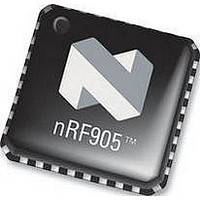
NRF905 NORDIC SEMICONDUCTOR, NRF905 Datasheet - Page 28

NRF905
Manufacturer Part Number
NRF905
Description
IC, TRANSCEIVER, 430 928MHZ, SMD
Manufacturer
NORDIC SEMICONDUCTOR
Datasheet
1.NRF905.pdf
(42 pages)
Specifications of NRF905
Transmitting Current
9mA
Data Rate
50Kbps
Frequency Range
430MHz To 928MHz
Modulation Type
GFSK
Sensitivity Dbm
-100dBm
Rf Ic Case Style
QFN
No. Of Pins
32
Supply Voltage Range
1.9V To 3.6V
Output Power
10dBm
Rohs Compliant
Yes
Lead Free Status / RoHS Status
Lead free / RoHS Compliant
Available stocks
Company
Part Number
Manufacturer
Quantity
Price
Part Number:
NRF905
Manufacturer:
NORDIC
Quantity:
20 000
Company:
Part Number:
NRF905-REEL
Manufacturer:
NORDIC
Quantity:
20 000
Part Number:
NRF905-REEL
Manufacturer:
NORDIC
Quantity:
20 000
Company:
Part Number:
NRF905C
Manufacturer:
NORDIC
Quantity:
10 615
PRODUCT SPECIFICATION
nRF905 Single Chip 433/868/915 MHz Radio Transceiver
9 nRF905 FEATURES
9.1
When the nRF905 is in ShockBurst
RF carrier is present at the channel the device is programmed to. This feature is very
effective to avoid collision of packets from different transmitters operating at the
same frequency. Whenever a device is ready to transmit it could first be set into
receive mode and sense whether or not the wanted channel is available for outgoing
data. This forms a very simple listen before transmit protocol. Operating Carrier
Detect (CD) with Reduced RX Power mode is an extremely power efficient RF
system. Typical Carrier Detect level (CD) is typically 5dB lower than sensitivity, i.e.
if sensitivity is –100dBm then the Carrier Detect function will sense a carrier wave as
low as –105dBm. Below –105dBm the Carrier Detect signal will be low, i.e. 0V.
Above –95dBm the Carrier Detect signal will be high, i.e. Vdd. Between
approximately -95 to -105 the Carrier Detect Signal will toggle.
9.2
When the nRF905 is in ShockBurst
high as soon as an incoming packet with an address that is identical with the device’s
own identity is received. With the Address Match pin the controller is alerted that the
nRF905 is receiving data actually before the Data Ready (DR) signal is set high. If the
Data Ready (DR) pin is not set high i.e. the CRC is incorrect then the Address Match
(AM) pin is reset to low at the end of the received data packet. This function can be
very useful for an MCU. If Address Match (AM) is high then the MCU can make a
decision to wait and see if Data Ready (DR) will be set high indicating a valid data
packet has been received or ignore that a possible packet is being received and switch
modes.
9.3
The Data Ready (DR) signal makes it possible to largely reduce the complexity of the
MCU software program.
In ShockBurst
is transmitted, telling the MCU that the nRF905 is ready for new actions. It is reset to
low at the start of a new packet transmission or when switched to a different mode i.e.
receive mode or standby mode.
In ShockBurst
beginning of the pre-amble and is set low at the end of the preamble. The Data Ready
(DR) signal therefore pulses at the beginning of each transmitted data packet.
In ShockBurst
i.e. a valid address, packet length and correct CRC. The MCU can then retrieve the
payload via the SPI interface. The Data Ready (DR) pin is reset to low once the data
has been clocked out of the data buffer or the device is switched to transmit mode.
Main office: Nordic Semiconductor ASA
Revision: 1.4
Carrier Detect.
Address Match
Data Ready
TM
TM
TM
RX, the signal is set high when nRF905 has received a valid packet,
TX, the Data Ready (DR) signal is set high when a complete packet
TX Auto Retransmit the Data Ready (DR) signal is set high at the
- Vestre Rosten 81, N-7075 Tiller, Norway
TM
TM
RX, the Carrier Detect (CD) pin is set high if a
RX mode, the Address Match (AM) pin is set
Page 28 of 42
- Phone +4772898900 -Fax +4772898989
June 2006


