ATS645LSH-I1 Allegro Microsystems Inc, ATS645LSH-I1 Datasheet - Page 4
ATS645LSH-I1
Manufacturer Part Number
ATS645LSH-I1
Description
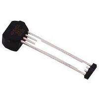
Hall Effect IC
Manufacturer
Allegro Microsystems Inc
Datasheet
1.ATS642LSHTN-I1-T.pdf
(14 pages)
Specifications of ATS645LSH-I1
Termination Type
Through Hole
No. Of Pins
4
Mounting Type
Through Hole
Hall Effect Type
Gear Tooth
Supply Voltage Min
4V
Peak Reflow Compatible (260 C)
No
Bandwidth
40kHz
Output Type
Digital
Filter Terminals
Through Hole
Rohs Compliant
No
Leaded Process Compatible
No
Package / Case
4-SIP
Lead Free Status / RoHS Status
Contains lead / RoHS non-compliant


ATS645LSH
OPERATING CHARACTERISTICS using reference target 60-0, T
ELECTRICAL CHARACTERISTICS
Supply Voltage
Undervoltage Lockout
Supply Zener Clamp Voltage
Supply Zener Current
Supply Current
Supply Current Ratio
POWER-ON STATE CHARACTERISTICS
Power-On State
Power-On Time
OUTPUT STAGE
Output Slew Rate
Continued on the next page.
CHARACTERISTIC
2
3
4
I
Symbol
V
I
I
CC(High)
I
CC(High)
CC(Low)
CC(Low)
POS
CC(UV)
dI/dt
V
t
V
I
PO
CC
Z
Z
/
True Zero Speed Miniature Differential Peak-
Operating; T
I
Test conditions only; V
ATS645LSH-I1
ATS645LSH-I2
ATS645LSH-I1
ATS645LSH-I2
Ratio of high current to low current
t > t
Target gear speed < 100 rpm
R
V
CC
LOAD
CC
= I
PO
0 → 5 V and 5 → 0 V
CC(max)
= 100 Ω, C
J
+ 3 mA; T
< 165 °C
Test Conditions
LOAD
A
Z
A
= 10 pF
and V
= 28 V
= 25°C
Detecting Gear Tooth Sensor IC
CC
within specifi cation, unless otherwise noted
Min.
12.0
1.85
11.8
4.0
4.0
5.9
115 Northeast Cutoff
1.508.853.5000; www.allegromicro.com
28
Allegro MicroSystems, Inc.
Worcester, Massachusetts 01615-0036 U.S.A.
–
–
–
–
–
I
CC(High)
Typ.
14.0
14.0
10
–
–
–
–
6
7
–
1
1
I
CC(max)
3 mA
Max.
16.0
16.8
3.05
4.0
8.0
8.4
24
–
–
2
–
+
mA/μs
Units
mA
mA
mA
mA
mA
ms
V
V
V
–
–
3
Related parts for ATS645LSH-I1
Image
Part Number
Description
Manufacturer
Datasheet
Request
R

Part Number:
Description:
IC, HALL EFFECT SENSOR, Linear, SOIC-8
Manufacturer:
Allegro Microsystems Inc
Datasheet:
Part Number:
Description:
IC, HALL EFFECT SENSOR, Linear, SOIC-8
Manufacturer:
Allegro Microsystems Inc
Datasheet:
Part Number:
Description:
IC, HALL EFFECT SENSOR, Linear, SOIC-8
Manufacturer:
Allegro Microsystems Inc
Datasheet:

Part Number:
Description:
IC SWITCH INTERFACE 2CHAN 8-SOIC
Manufacturer:
Allegro Microsystems Inc
Datasheet:

Part Number:
Description:
IC SMOKE DETECTOR ION 16-DIP
Manufacturer:
Allegro Microsystems Inc
Datasheet:
Part Number:
Description:
IC SMOKE DETECTOR ION 16-DIP
Manufacturer:
Allegro Microsystems Inc
Datasheet:
Part Number:
Description:
IC SMOKE DETECTOR ION 16-DIP
Manufacturer:
Allegro Microsystems Inc
Datasheet:
Part Number:
Description:
IC SMOKE DETECTOR PHOTO 16-DIP
Manufacturer:
Allegro Microsystems Inc
Datasheet:
Part Number:
Description:
IC SMOKE DETECTOR ION 16-DIP
Manufacturer:
Allegro Microsystems Inc
Datasheet:
Part Number:
Description:
IC SMOKE DETECTOR PHOTO 16-DIP
Manufacturer:
Allegro Microsystems Inc
Datasheet:
Part Number:
Description:
IC SMOKE DETECTOR PHOTO 16-DIP
Manufacturer:
Allegro Microsystems Inc
Datasheet:
Part Number:
Description:
IC SMOKE DETECTOR ION 16-DIP
Manufacturer:
Allegro Microsystems Inc
Datasheet:
Part Number:
Description:
IC SMOKE DETECTOR PHOTO 16-SOIC
Manufacturer:
Allegro Microsystems Inc
Datasheet:

Part Number:
Description:
IC LED DRIVER HIGH BRIGHT 16-QFN
Manufacturer:
Allegro Microsystems Inc
Datasheet:

Part Number:
Description:
IC LED DRIVER AUTOMOTIVE 8-SOIC
Manufacturer:
Allegro Microsystems Inc
Datasheet: