ATS645LSH-I1 Allegro Microsystems Inc, ATS645LSH-I1 Datasheet - Page 8
ATS645LSH-I1
Manufacturer Part Number
ATS645LSH-I1
Description
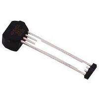
Hall Effect IC
Manufacturer
Allegro Microsystems Inc
Datasheet
1.ATS642LSHTN-I1-T.pdf
(14 pages)
Specifications of ATS645LSH-I1
Termination Type
Through Hole
No. Of Pins
4
Mounting Type
Through Hole
Hall Effect Type
Gear Tooth
Supply Voltage Min
4V
Peak Reflow Compatible (260 C)
No
Bandwidth
40kHz
Output Type
Digital
Filter Terminals
Through Hole
Rohs Compliant
No
Leaded Process Compatible
No
Package / Case
4-SIP
Lead Free Status / RoHS Status
Contains lead / RoHS non-compliant


ATS645LSH
THERMAL CHARACTERISTICS may require derating at maximum conditions, see application information
*Additional information is available on the Allegro Web site.
Package Thermal Resistance
CHARACTERISTIC
1900
1800
1700
1600
1500
1400
1300
1200
1100
1000
Symbol
900
800
700
600
500
400
300
200
100
True Zero Speed Miniature Differential Peak-
R
25
24
23
22
21
20
19
18
17
16
15
14
13
12
11
10
0
9
8
7
6
5
4
3
2
20
θJA
20
T
40
40
J(max)
Single-layer PCB with copper limited to solder pads
Two-layer PCB with 3.8 in.
nected with thermal vias and to device ground pin
Maximum Power Dissipation, P
T
J(max)
60
= 165ºC; V
60
(R
Power Derating Curve
(R
θJA
θJA
= 165ºC; I
80
= 84 ºC/W)
= 126 ºC/W)
Temperature (°C)
Temperature (ºC)
80
CC
100
= V
100
Detecting Gear Tooth Sensor IC
CC
CC(max)
TEST CONDITIONS*
= I
120
120
CC(max)
; I
2
CC
of copper area on each side con-
140
140
= I
D(max)
CC(max)
160
160
180
180
V
V
115 Northeast Cutoff
1.508.853.5000; www.allegromicro.com
Allegro MicroSystems, Inc.
Worcester, Massachusetts 01615-0036 U.S.A.
CC(max)
CC(min)
Value
126
84
Units
ºC/W
ºC/W
7
Related parts for ATS645LSH-I1
Image
Part Number
Description
Manufacturer
Datasheet
Request
R

Part Number:
Description:
IC, HALL EFFECT SENSOR, Linear, SOIC-8
Manufacturer:
Allegro Microsystems Inc
Datasheet:
Part Number:
Description:
IC, HALL EFFECT SENSOR, Linear, SOIC-8
Manufacturer:
Allegro Microsystems Inc
Datasheet:
Part Number:
Description:
IC, HALL EFFECT SENSOR, Linear, SOIC-8
Manufacturer:
Allegro Microsystems Inc
Datasheet:

Part Number:
Description:
IC SWITCH INTERFACE 2CHAN 8-SOIC
Manufacturer:
Allegro Microsystems Inc
Datasheet:

Part Number:
Description:
IC SMOKE DETECTOR ION 16-DIP
Manufacturer:
Allegro Microsystems Inc
Datasheet:
Part Number:
Description:
IC SMOKE DETECTOR ION 16-DIP
Manufacturer:
Allegro Microsystems Inc
Datasheet:
Part Number:
Description:
IC SMOKE DETECTOR ION 16-DIP
Manufacturer:
Allegro Microsystems Inc
Datasheet:
Part Number:
Description:
IC SMOKE DETECTOR PHOTO 16-DIP
Manufacturer:
Allegro Microsystems Inc
Datasheet:
Part Number:
Description:
IC SMOKE DETECTOR ION 16-DIP
Manufacturer:
Allegro Microsystems Inc
Datasheet:
Part Number:
Description:
IC SMOKE DETECTOR PHOTO 16-DIP
Manufacturer:
Allegro Microsystems Inc
Datasheet:
Part Number:
Description:
IC SMOKE DETECTOR PHOTO 16-DIP
Manufacturer:
Allegro Microsystems Inc
Datasheet:
Part Number:
Description:
IC SMOKE DETECTOR ION 16-DIP
Manufacturer:
Allegro Microsystems Inc
Datasheet:
Part Number:
Description:
IC SMOKE DETECTOR PHOTO 16-SOIC
Manufacturer:
Allegro Microsystems Inc
Datasheet:

Part Number:
Description:
IC LED DRIVER HIGH BRIGHT 16-QFN
Manufacturer:
Allegro Microsystems Inc
Datasheet:

Part Number:
Description:
IC LED DRIVER AUTOMOTIVE 8-SOIC
Manufacturer:
Allegro Microsystems Inc
Datasheet: