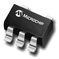
MCP6541T-I/LT Microchip Technology, MCP6541T-I/LT Datasheet - Page 13

MCP6541T-I/LT
Manufacturer Part Number
MCP6541T-I/LT
Description
IC,VOLT COMPARATOR,SINGLE,CMOS,TSSOP,6PIN,PLASTIC
Manufacturer
Microchip Technology
Type
General Purposer
Specifications of MCP6541T-I/LT
Rohs Compliant
YES
Number Of Elements
1
Output Type
CMOS, Push-Pull, Rail-to-Rail, TTL
Voltage - Supply
1.6 V ~ 5.5 V
Mounting Type
Surface Mount
Package / Case
6-TSSOP (5 lead), SC-88A, SOT-353
Comparator Type
General Purpose
No. Of Comparators
1
Response Time
4µs
Ic Output Type
CMOS, Push Pull, TTL
Supply Current
600nA
Supply Voltage Range
1.6V To 5.5V
Output Compatibility
CMOS, TTL
Lead Free Status / RoHS Status
Lead free / RoHS Compliant
Other names
MCP6541T-I/LT
MCP6541T-I/LTTR
MCP6541T-I/LTTR
Available stocks
Company
Part Number
Manufacturer
Quantity
Price
Company:
Part Number:
MCP6541T-I/LT
Manufacturer:
Microchip Technology
Quantity:
29 376
Part Number:
MCP6541T-I/LT
Manufacturer:
MICROCHIP/微芯
Quantity:
20 000
4.4.1
Figure 4-3 shows a non-inverting circuit for single-
supply applications using just two resistors. The
resulting hysteresis diagram is shown in Figure 4-4.
FIGURE 4-3:
hysteresis for single-supply.
FIGURE 4-4:
Non-Inverting Circuit.
The trip points for Figures 4-3 and 4-4 are:
EQUATION 4-1:
© 2006 Microchip Technology Inc.
V
V
V
V
V
V
TLH
THL
OH
DD
OL
SS
V
V
IN
= trip voltage from low to high
= trip voltage from high to low
SS
V
V THL
V TLH
High-to-Low
V
REF
OUT
NON-INVERTING CIRCUIT
R
=
=
1
V REF 1
V REF 1
V
THL
Non-inverting circuit with
Hysteresis Diagram for the
+
⎛
⎜
⎝
⎛
⎜
⎝
-
MCP654X
V
+
+
TLH
V
------ -
R F
------ -
R F
R 1
R 1
DD
Low-to-High
⎞
⎟
⎠
⎞
⎟
⎠
R
–
–
F
V OH
V OL
⎛
⎜
⎝
⎛
⎜
⎝
V
------ -
R F
R 1
R 1
------ -
R F
DD
⎞
⎟
⎠
⎞
⎟
⎠
V
OUT
V
IN
4.4.2
Figure 4-5 shows an inverting circuit for single-supply
using three resistors. The resulting hysteresis diagram
is shown in Figure 4-6.
FIGURE 4-5:
Hysteresis.
FIGURE 4-6:
Inverting Circuit.
In order to determine the trip voltages (V
for the circuit shown in Figure 4-5, R
simplified to the Thevenin equivalent circuit with
respect to V
FIGURE 4-7:
V
V
V
V
OH
DD
OL
SS
V
V
23
SS
V
IN
R
R
Low-to-High
V
2
3
OUT
V
INVERTING CIRCUIT
DD
DD
, as shown in Figure 4-7.
R
MCP6541/2/3/4
23
V
MCP654X
TLH
Inverting Circuit With
Hysteresis Diagram for the
Thevenin Equivalent Circuit.
V
+
-
MCP654X
DD
V
THL
V
DD
R
F
High-to-Low
V
R
SS
F
DS21696D-page 13
2
and R
THL
V
V
DD
OUT
and V
V
3
OUT
can be
V
IN
TLH
)


