PIC16F685-I/ML Microchip Technology, PIC16F685-I/ML Datasheet - Page 162
PIC16F685-I/ML
Manufacturer Part Number
PIC16F685-I/ML
Description
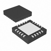
IC,MICROCONTROLLER,8-BIT,PIC CPU,CMOS,LLCC,20PIN,PLASTIC
Manufacturer
Microchip Technology
Series
PIC® 16Fr
Datasheets
1.PIC16F616T-ISL.pdf
(8 pages)
2.PIC16F690DM-PCTLHS.pdf
(306 pages)
3.PIC16F677-IP.pdf
(2 pages)
4.PIC16F677-IP.pdf
(16 pages)
Specifications of PIC16F685-I/ML
Rohs Compliant
YES
Core Processor
PIC
Core Size
8-Bit
Speed
20MHz
Peripherals
Brown-out Detect/Reset, POR, PWM, WDT
Number Of I /o
18
Program Memory Size
7KB (4K x 14)
Program Memory Type
FLASH
Eeprom Size
256 x 8
Ram Size
256 x 8
Voltage - Supply (vcc/vdd)
2 V ~ 5.5 V
Data Converters
A/D 12x10b
Oscillator Type
Internal
Operating Temperature
-40°C ~ 85°C
Package / Case
20-VQFN Exposed Pad, 20-HVQFN, 20-SQFN, 20-DHVQFN
Lead Free Status / RoHS Status
Lead free / RoHS Compliant
For Use With
AC164324 - MODULE SKT FOR MPLAB 8DFN/16QFNAC162061 - HEADER INTRFC MPLAB ICD2 20PINDVA1004 - DEVICE ADAPTER 8/14/20DIP
Connectivity
-
Lead Free Status / RoHS Status
Lead free / RoHS Compliant


PIC16F631/677/685/687/689/690
12.2
The factory calibrates the internal oscillator block out-
put (INTOSC). However, the INTOSC frequency may
drift as V
affects the asynchronous baud rate. Two methods may
be used to adjust the baud rate clock, but both require
a reference clock source of some kind.
REGISTER 12-1:
DS41262E-page 160
bit 7
Legend:
R = Readable bit
-n = Value at POR
bit 7
bit 6
bit 5
bit 4
bit 3
bit 2
bit 1
bit 0
Note 1:
R/W-0
CSRC
Clock Accuracy with
Asynchronous Operation
DD
SREN/CREN overrides TXEN in Sync mode.
or temperature changes, and this directly
CSRC: Clock Source Select bit
Asynchronous mode:
Don’t care
Synchronous mode:
1 =
0 =
TX9: 9-bit Transmit Enable bit
1 =
0 =
TXEN: Transmit Enable bit
1 = Transmit enabled
0 = Transmit disabled
SYNC: EUSART Mode Select bit
1 = Synchronous mode
0 = Asynchronous mode
SENDB: Send Break Character bit
Asynchronous mode:
1 = Send Sync Break on next transmission (cleared by hardware upon completion)
0 = Sync Break transmission completed
Synchronous mode:
Don’t care
BRGH: High Baud Rate Select bit
Asynchronous mode:
1 = High speed
0 = Low speed
Synchronous mode:
Unused in this mode
TRMT: Transmit Shift Register Status bit
1 = TSR empty
0 = TSR full
TX9D: Ninth bit of Transmit Data
Can be address/data bit or a parity bit.
R/W-0
TX9
Master mode (clock generated internally from BRG)
Slave mode (clock from external source)
Selects 9-bit transmission
Selects 8-bit transmission
TXSTA: TRANSMIT STATUS AND CONTROL REGISTER
W = Writable bit
‘1’ = Bit is set
TXEN
R/W-0
(1)
(1)
R/W-0
SYNC
U = Unimplemented bit, read as ‘0’
‘0’ = Bit is cleared
SENDB
R/W-0
The first (preferred) method uses the OSCTUNE
register to adjust the INTOSC output. Adjusting the
value in the OSCTUNE register allows for fine resolution
changes to the system clock source. See Section 3.5
“Internal Clock Modes” for more information.
The other method adjusts the value in the Baud Rate
Generator. This can be done automatically with the
Auto-Baud
“Auto-Baud Detect”). There may not be fine enough
resolution when adjusting the Baud Rate Generator to
compensate for a gradual change in the peripheral
clock frequency.
Detect
BRGH
R/W-0
feature
© 2008 Microchip Technology Inc.
x = Bit is unknown
TRMT
R-1
(see
Section 12.3.1
R/W-0
TX9D
bit 0
Related parts for PIC16F685-I/ML
Image
Part Number
Description
Manufacturer
Datasheet
Request
R

Part Number:
Description:
IC PIC MCU FLASH 4KX14 20SSOP
Manufacturer:
Microchip Technology
Datasheet:

Part Number:
Description:
IC PIC MCU FLASH 4KX14 20DIP
Manufacturer:
Microchip Technology
Datasheet:

Part Number:
Description:
IC PIC MCU FLASH 4KX14 20SOIC
Manufacturer:
Microchip Technology
Datasheet:
Part Number:
Description:
IC PIC MCU FLASH 4KX14 20SSOP
Manufacturer:
Microchip Technology
Datasheet:
Part Number:
Description:
IC PIC MCU FLASH 4KX14 20SOIC
Manufacturer:
Microchip Technology
Datasheet:
Part Number:
Description:
IC PIC MCU FLASH 4KX14 20DIP
Manufacturer:
Microchip Technology
Datasheet:

Part Number:
Description:
IC,MICROCONTROLLER,8-BIT,PIC CPU,CMOS,LLCC,20PIN,PLASTIC
Manufacturer:
Microchip Technology
Datasheet:

Part Number:
Description:
IC, 8BIT MCU, PIC16F, 32MHZ, SOIC-18
Manufacturer:
Microchip Technology
Datasheet:

Part Number:
Description:
IC, 8BIT MCU, PIC16F, 32MHZ, SSOP-20
Manufacturer:
Microchip Technology
Datasheet:

Part Number:
Description:
IC, 8BIT MCU, PIC16F, 32MHZ, DIP-18
Manufacturer:
Microchip Technology
Datasheet:

Part Number:
Description:
IC, 8BIT MCU, PIC16F, 32MHZ, QFN-28
Manufacturer:
Microchip Technology
Datasheet:

Part Number:
Description:
IC, 8BIT MCU, PIC16F, 32MHZ, QFN-28
Manufacturer:
Microchip Technology
Datasheet:
Part Number:
Description:
IC, 8BIT MCU, PIC16F, 32MHZ, QFN-28
Manufacturer:
Microchip Technology
Datasheet:
Part Number:
Description:
IC, 8BIT MCU, PIC16F, 32MHZ, SSOP-20
Manufacturer:
Microchip Technology
Datasheet:

Part Number:
Description:
IC, 8BIT MCU, PIC16F, 20MHZ, DIP-40
Manufacturer:
Microchip Technology
Datasheet: