PIC16F785T-I/ML Microchip Technology, PIC16F785T-I/ML Datasheet - Page 131
PIC16F785T-I/ML
Manufacturer Part Number
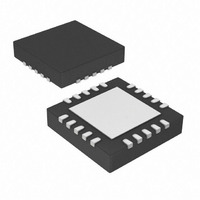
PIC16F785T-I/ML
Description
3.5 KB Flash, 128 RAM, 18 I/O 20 QFN 4x4mm T/R
Manufacturer
Microchip Technology
Series
PIC® 16Fr
Datasheets
1.PIC16F616T-ISL.pdf
(8 pages)
2.PIC16F785-ISS.pdf
(206 pages)
3.PIC16F785-ISS.pdf
(10 pages)
4.PIC16F785-ISS.pdf
(28 pages)
Specifications of PIC16F785T-I/ML
Core Processor
PIC
Core Size
8-Bit
Speed
20MHz
Peripherals
Brown-out Detect/Reset, POR, PWM, WDT
Number Of I /o
17
Program Memory Size
3.5KB (2K x 14)
Program Memory Type
FLASH
Eeprom Size
256 x 8
Ram Size
128 x 8
Voltage - Supply (vcc/vdd)
2 V ~ 5.5 V
Data Converters
A/D 14x10b
Oscillator Type
Internal
Operating Temperature
-40°C ~ 85°C
Package / Case
20-VQFN Exposed Pad, 20-HVQFN, 20-SQFN, 20-DHVQFN
Lead Free Status / RoHS Status
Lead free / RoHS Compliant
Connectivity
-
Lead Free Status / RoHS Status
Lead free / RoHS Compliant, Lead free / RoHS Compliant


17.2
ADDLW
Syntax:
Operands:
Operation:
Status Affected:
Description:
ADDWF
Syntax:
Operands:
Operation:
Status Affected:
Description:
ANDLW
Syntax:
Operands:
Operation:
Status Affected:
Description:
© 2008 Microchip Technology Inc.
Instruction Descriptions
Add W and f
[label] ADDWF
0 ≤ f ≤ 127
d ∈ [0,1]
(W) + (f) → (destination)
C, DC, Z
Add the contents of the W register
with register ‘f’. If ‘d’ is ‘0’, the
result is stored in the W register. If
‘d’ is ‘1’, the result is stored back
in register ‘f’.
[label] ADDLW
0 ≤ k ≤ 255
(W) + k → (W)
C, DC, Z
The contents of the W register
are added to the eight-bit literal ‘k’
and the result is placed in the W
register.
[label] ANDLW
0 ≤ k ≤ 255
(W) .AND. (k) → (W)
Z
The contents of W register are
AND’ed with the eight-bit literal
‘k’. The result is placed in the W
register.
Add Literal and W
AND Literal with W
k
f,d
k
ANDWF
Syntax:
Operands:
Operation:
Status Affected:
Description:
BCF
Syntax:
Operands:
Operation:
Status Affected:
Description:
BSF
Syntax:
Operands:
Operation:
Status Affected:
Description:
PIC16F785/HV785
AND W with f
[label] ANDWF
0 ≤ f ≤ 127
d ∈ [0,1]
(W) .AND. (f) → (destination)
Z
AND the W register with register
‘f’. If ‘d’ is ‘0’, the result is stored in
the W register. If ‘d’ is ‘1’, the
result is stored back in register ‘f’.
Bit Clear f
[label] BCF
0 ≤ f ≤ 127
0 ≤ b ≤ 7
0 → (f<b>)
None
Bit ‘b’ in register ‘f’ is cleared.
Bit Set f
[label] BSF
0 ≤ f ≤ 127
0 ≤ b ≤ 7
1 → (f<b>)
None
Bit ‘b’ in register ‘f’ is set.
f,b
f,b
DS41249E-page 129
f,d
Related parts for PIC16F785T-I/ML
Image
Part Number
Description
Manufacturer
Datasheet
Request
R

Part Number:
Description:
IC PIC MCU FLASH 2KX14 20SOIC
Manufacturer:
Microchip Technology
Datasheet:

Part Number:
Description:
IC PIC MCU FLASH 2KX14 20QFN
Manufacturer:
Microchip Technology
Datasheet:

Part Number:
Description:
IC PIC MCU FLASH 2KX14 20DIP
Manufacturer:
Microchip Technology
Datasheet:

Part Number:
Description:
IC PIC MCU FLASH 2KX14 20SSOP
Manufacturer:
Microchip Technology
Datasheet:
Part Number:
Description:
IC PIC MCU FLASH 2KX14 20SOIC
Manufacturer:
Microchip Technology
Datasheet:
Part Number:
Description:
IC PIC MCU FLASH 2KX14 20DIP
Manufacturer:
Microchip Technology
Datasheet:
Part Number:
Description:
3.5 KB Flash, 128 RAM, 18 I/O 20 QFN 4x4mm TUBE
Manufacturer:
Microchip Technology
Datasheet:
Part Number:
Description:
20 PIN, 3.5 KB STD FLASH, 128 RAM, 18 I/O PB FREE,
Manufacturer:
Microchip Technology
Datasheet:

Part Number:
Description:
IC, 8BIT MCU, PIC16F, 32MHZ, SOIC-18
Manufacturer:
Microchip Technology
Datasheet:

Part Number:
Description:
IC, 8BIT MCU, PIC16F, 32MHZ, SSOP-20
Manufacturer:
Microchip Technology
Datasheet:

Part Number:
Description:
IC, 8BIT MCU, PIC16F, 32MHZ, DIP-18
Manufacturer:
Microchip Technology
Datasheet:

Part Number:
Description:
IC, 8BIT MCU, PIC16F, 32MHZ, QFN-28
Manufacturer:
Microchip Technology
Datasheet:

Part Number:
Description:
IC, 8BIT MCU, PIC16F, 32MHZ, QFN-28
Manufacturer:
Microchip Technology
Datasheet:
Part Number:
Description:
IC, 8BIT MCU, PIC16F, 32MHZ, QFN-28
Manufacturer:
Microchip Technology
Datasheet:
Part Number:
Description:
IC, 8BIT MCU, PIC16F, 32MHZ, SSOP-20
Manufacturer:
Microchip Technology
Datasheet: