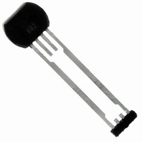
ATS682LSHTN-T Allegro Microsystems Inc, ATS682LSHTN-T Datasheet - Page 11

ATS682LSHTN-T
Manufacturer Part Number
ATS682LSHTN-T
Description
IC HALL EFFECT SENSOR 4SIP
Manufacturer
Allegro Microsystems Inc
Type
Linear Field Sensorr
Datasheet
1.ATS682LSHTN-T.pdf
(16 pages)
Specifications of ATS682LSHTN-T
Package / Case
4-SIP
Sensing Range
120mV Trip, 120mV Release
Voltage - Supply
4 V ~ 24 V
Current - Supply
16.8mA
Output Type
Analog
Features
Gear Tooth Type
Operating Temperature
-40°C ~ 150°C
Bandwidth
40kHz
Supply Voltage Max
24V
Hall Effect Type
Gear Tooth
Operating Temperature Range
-40°C To +150°C
Supply Voltage Min
4V
Lead Free Status / RoHS Status
Lead free / RoHS Compliant
Current - Output (max)
-
Lead Free Status / RoHS Status
Lead free / RoHS Compliant, Lead free / RoHS Compliant
Other names
620-1327-2
Available stocks
Company
Part Number
Manufacturer
Quantity
Price
Company:
Part Number:
ATS682LSHTN-T
Manufacturer:
ST
Quantity:
101
ATS682LSH
Power Supply Protection
The device contains an on-chip regulator and can operate over a
wide V
lated power supply, transient protection must be added externally.
For applications using a regulated line, EMI/RFI protection may
still be required. Contact Allegro for information on the circuitry
needed for compliance with various EMC specifications. Refer to
figure 7 for an example of a basic application circuit.
Undervoltage Lockout
When the supply voltage falls below the undervoltage lockout
threshold, V
output state returns to the Power-On State (POS) until sufficient
V
V
Assembly Description
This device is molded into a plastic body that has been optimized
for size, ease of assembly, and manufacturability. High operat-
Figure 7. Typical application circuit
CC
CC
is supplied. I
< V
CC
CC
range. For devices that need to operate from an unregu-
(min).
CC(UV)
Test pin floating
CC
ECU
, the device enters Reset mode, where the
levels may not meet datasheet limits when
V+
100
R
SE
NSE
ATS682
GND
VCC
4
1
C
LOAD
C
0.01
BYP
μF
Miniature, Two-Wire, True Zero Speed
Differential Peak-Detecting Sensor IC
ing temperature materials are used in all aspects of construction.
Refer to the Allegro website, www.allegromicro.com, for more
specific applications notes on finished package processing.
Diagnostics
The regulated current output is configured for two-wire applica-
tions, requiring one less wire for operation than do switches with
the traditional open-collector output. Additionally, the system
designer inherently gains diagnostics because there is always
output current flowing, which should be in either of two nar-
row ranges, shown in figure 8 as I
current level not within these ranges indicates a fault condition.
If I
< I
between the allowed ranges for I
a general fault condition.
Figure 8. Diagnostic characteristics of supply current values
CC(LOW)
CC
> I
I
I
I
I
CC(HIGH)
CC(HIGH)
CC(LOW)
CC(LOW)
CC(HIGH)
(min), then an open condition exists. Any value of I
(max)
(min)
(max)
(min)
+mA
(max), then a short condition exists, and if I
0
Short
Open
Fault
115 Northeast Cutoff
1.508.853.5000; www.allegromicro.com
Allegro MicroSystems, Inc.
Worcester, Massachusetts 01615-0036 U.S.A.
CC(HIGH)
CC(HIGH)
Range for Valid I
Range for Valid I
and I
and I
CC(LOW)
CC(LOW)
CC(HIGH)
CC(LOW)
indicates
. Any
CC
CC
11


