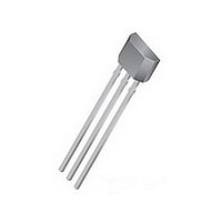
A1201EUA-T Allegro Microsystems Inc, A1201EUA-T Datasheet - Page 4

A1201EUA-T
Manufacturer Part Number
A1201EUA-T
Description
IC SW CONTINUE TIME BIPO 3-SIP
Manufacturer
Allegro Microsystems Inc
Type
Bipolar Latchr
Datasheet
1.A1203EUA-T.pdf
(13 pages)
Specifications of A1201EUA-T
Sensing Range
50G Trip, -50G Release
Voltage - Supply
3.8 V ~ 24 V
Current - Supply
7.5mA
Current - Output (max)
25mA
Output Type
Digital, Open Drain
Features
Regulated Voltage
Operating Temperature
-40°C ~ 85°C
Package / Case
3-SIP
Magnetic Type
Bipolar
Operating Supply Voltage (min)
3.8V
Operating Supply Voltage (typ)
5/9/12/15/18V
Operating Supply Voltage (max)
24V
Output Current
25mA
Mag Sensor Operate Point (g)
50Gs
Mag Sensor Release Point (g)
-50Gs
Mag Sensor Hysteresis(g)
30Gs
Package Type
Ultra Mini SIP
Pin Count
3
Mounting
Through Hole
Operating Temp Range
-40C to 85C
Operating Temperature Classification
Industrial
Lead Free Status / RoHS Status
Lead free / RoHS Compliant
A1201
OPERATING CHARACTERISTICS over full operating voltage and ambient temperature ranges, unless otherwise noted
Electrical Characteristics
Supply Voltage
Output Leakage Current
Output On Voltage
Power-On Time
Output Rise Time
Output Fall Time
Supply Current
Reverse Battery Current
Supply Zener Clamp Voltage
Supply Zener Current
Magnetic Characteristics
1
2
3
4
5
This so-called algebraic convention supports arithmetic comparison of north and south polarity values, where the relative strength of the field is indicated
by the absolute value of B, and the sign indicates the polarity of the field (for example, a –100 G field and a 100 G field have equivalent strength, but
opposite polarity).
Operate Point
Release Point
Hysteresis
Maximum voltage must be adjusted for power dissipation and junction temperature, see Power Derating section.
For V
C
Maximum current limit is equal to the maximum I
Magnetic flux density, B, is indicated as a negative value for north-polarity magnetic fields, and as a positive value for south-polarity magnetic fields.
S
=oscilloscope probe capacitance.
CC
Characteristic
slew rates greater than 250 V/μs, and T
1
2
3
3
4
5
V
Symbol
I
I
OUTOFF
OUT(SAT)
I
EMC (Electromagnetic Compatibility) REQUIREMENTS
CCOFF
B
CCON
I
V
B
B
t
RCC
V
PO
HYS
I
CC
t
t
OP
RP
Z
r
f
Z
A
CC(max)
= 150°C, the Power-On Time can reach its maximum value.
DEVICE QUALIFICATION PROGRAM
Operating, T
V
I
Slew rate (dV
or B < B
V
V
B > B
B < B
V
I
V
OUT
CC
OUT
CC
CC
RCC
Z
A1201
A1201
A1201
= 32 V; T
Contact Allegro for information.
Contact Allegro for information.
= 30 mA; T
+ 22 mA.
= 12 V, R
= 12 V, R
= 20 mA, B > B
= 24 V, B < B
OP
RP
= –30 V
RP
(min) – 5 G
A
J
South pole adjacent to branded face
of device
North pole adjacent to branded face
of device
B
CC
LOAD
LOAD
= 25°C
< 165°C
A
OP
/dt) < 2.5 V/μs, B > B
= 25°C
Test Conditions
– B
RP
= 820 Ω, C
= 820 Ω, C
OP
Continuous-Time Bipolar Switch
RP
S
S
= 12 pF
= 12 pF
OP
(max) + 5 G
115 Northeast Cutoff, Box 15036
Allegro MicroSystems, Inc.
Worcester, Massachusetts 01615-0036 (508) 853-5000
www.allegromicro.com
Min.
–40
–50
3.8
32
–
–
–
–
–
–
–
–
–
5
Typ.
215
–15
3.8
3.5
15
30
–
–
–
–
–
–
–
–
Max.
400
–10
7.5
7.5
24
30
50
40
55
10
4
2
2
–
Units
mV
mA
mA
mA
mA
μA
μs
μs
μs
V
V
G
G
G
4


