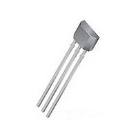
A3245LUA Allegro Microsystems Inc, A3245LUA Datasheet - Page 9

A3245LUA
Manufacturer Part Number
A3245LUA
Description
IC SW HALL EFFECT OMNI 3-SIP
Manufacturer
Allegro Microsystems Inc
Type
Omnipolar Switchr
Specifications of A3245LUA
Sensing Range
±55G Trip, ±6G Release
Voltage - Supply
3.6 V ~ 24 V
Current - Supply
3.5mA
Output Type
Digital, Open Drain
Features
Regulated Voltage
Operating Temperature
-40°C ~ 150°C
Package / Case
3-SIP
Magnetic Type
Omnipolar
Operating Supply Voltage (min)
3.6V
Operating Supply Voltage (typ)
5/9/12/15/18V
Operating Supply Voltage (max)
24V
Mag Sensor Operate Point (g)
-15/55Gs
Mag Sensor Release Point (g)
-50/5Gs
Mag Sensor Hysteresis(g)
18Gs
Package Type
Ultra Mini SIP
Pin Count
3
Mounting
Through Hole
Operating Temp Range
-40C to 150C
Operating Temperature Classification
Automotive
Lead Free Status / RoHS Status
Contains lead / RoHS non-compliant
Current - Output (max)
-
Lead Free Status / RoHS Status
Not Compliant, Contains lead / RoHS non-compliant
A3245
Operation
The output of this device switches low (turns on) when a mag-
netic fi eld perpendicular to the Hall element exceeds the oper-
ate point, B
voltage is V
ing current up to the short circuit current limit, I
minimum of 30 mA. When the magnetic fi eld is reduced below
the release point, B
output switches high (turns off). The difference in the magnetic
operate and release points is the hysteresis, B
This built-in hysteresis allows clean switching of the output even
in the presence of external mechanical vibration and electrical
noise.
Powering-on the device in a hysteresis region, between B
and B
is attained after the fi rst excursion beyond B
Applications
It is strongly recommended that an external bypass capacitor be
connected (in close proximity to the Hall element) between the
Figure 1: Switching Behavior of Omnipolar Switches. In Panel A, on the horizontal axis, the B+ direction indicates increasing south polarity
magnetic fi eld strength, and the B– direction indicates decreasing south polarity fi eld strength (including the case of increasing north
polarity). This behavior can be exhibited when using a circuit such as that shown in panel B.
V+
RPX
0
B–
, allows an indeterminate output state. The correct state
OPS
OUT(SAT)
(or is less than B
B
HYS
RPS
. The output transistor is capable of sink-
(or increased above B
(A)
0
OPN
Chopper-Stabilized Omnipolar Hall Effect Switches
). After turn-on, the output
B
HYS
OPX
RPN
HYS
OM
or B
), the device
, of the device.
Functional Description
, which is a
B+
RPX
V
V
.
OPX
S
OUT(SAT)
supply and ground of the device to reduce both external noise
and noise generated by the chopper stabilization technique. As is
shown in Panel B of fi gure 1, a 0.1μF capacitor is typical.
Omnipolar switches allow operation with either a north pole or
south pole magnet orientation, enhancing product manufactur-
ability with the device.
Extensive applications information on magnets and Hall-effect
devices is available in:
• Hall-Effect IC Applications Guide, AN27701,
• Hall-Effect Devices: Gluing, Potting, Encapsulating, Lead
• Soldering Methods for Allegro’s Products – SMT and Through-
All are provided in Allegro Electronic Data Book, AMS-702 and
the Allegro Web site: www.allegromicro.com
Welding and Lead Forming, AN27703.1
Hole, AN26009
V
S
C
0.1 µF
BYP
115 Northeast Cutoff, Box 15036
Allegro MicroSystems, Inc.
Worcester, Massachusetts 01615-0036 (508) 853-5000
www.allegromicro.com
A3245
(B)
VCC
GND
VOUT
R
LOAD
Output
8


