QS30LDLQ BANNER ENGINEERING, QS30LDLQ Datasheet - Page 6
QS30LDLQ
Manufacturer Part Number
QS30LDLQ
Description
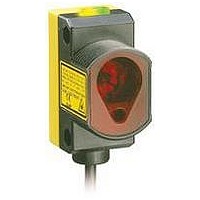
Photoelectric Sensor
Manufacturer
BANNER ENGINEERING
Type
Laserr
Specifications of QS30LDLQ
Output Current
150mA
Sensor Output
NPN/PNP
Supply Voltage Range Dc
10V To 30V
Sensor Housing
Rectangular
Sensor Input
Laser
Body Material
ABS Plastic
Supply Voltage Max
30VDC
Sensing Range Max
800mm
Brand/series
QS30
Current, Switching
150 mA
Function
Proximity
Ip Rating
IP67
Mounting Type
Threaded
Output
NPN/PNP
Primary Type
Photoelectric
Range, Measurement
800 mm
Sensing Mode
Diffuse
Technology
Photoelectric
Termination
5-Wire Connector
Voltage, Supply
30 VDC
Lead Free Status / Rohs Status
RoHS Exempt Product


QS30 Series Diffuse-Mode Laser Sensor
Dynamic TEACH is best used when a machine or process may not be stopped for
teaching. A variation of two-point TEACH, it programs the sensor during actual
machine run conditions, taking multiple samples of the light and dark conditions and
automatically setting the threshold at the optimum level (see Figure 3).
Dynamic TEACH activates the sensor’s adaptive threshold system, which continuously
tracks minimum and maximum signal levels, and automatically maintains centering of
the switch point between the light and dark conditions. The adaptive threshold system
remains in effect during RUN mode. The adaptive routine saves to non-volatile
memory at least once per hour.
When Dynamic TEACH mode is used, the Output ON state (light or dark operate) will
remain as it was last programmed. To change the Output ON state, use SETUP mode
(see page 8).
The sensing set point may be adjusted (fine-tuned) whenever the sensor is in RUN
mode by clicking the “+” and “-” buttons. However, when a manual adjustment is
made, the adaptive threshold system is disabled (cancelled).
6
Dynamic TEACH and Adaptive Thresholds
• Teach on-the-fly
• Sets a single switching threshold
• Threshold position is adjustable using “+” and “-” buttons (Manual Adjust)
P/N 109027 rev. C
• Press and Hold
• Present Output
• Continue to hold
• Release
ON and OFF
conditions
Push Button
• Hold remote line
• Present Output ON
• Continue to hold
• Release remote
low (to ground)
and OFF conditions
remote line low (to
ground)
line/switch
Remote Line
Power LED: OFF
Bargraph: #7 & 8 flashing
Power LED: OFF
Bargraph: #7 & 8 flashing
Teach Accepted
Power LED: ON
Bargraph: One LED flashes to show
Sensor returns to RUN mode with
new settings
Teach Unacceptable
Power LED: OFF
Bargraph: #1, 3, 6, 8 flash to show fail
Sensor returns to RUN mode
without changing settings
relative contrast (good contrast
shown; see table above)
Banner Engineering Corp.
www.bannerengineering.com • Tel: 763.544.3164
Display Shows
Figure 3. Two-Point Dynamic TEACH
(no signal)
Bargraph
Number
Darkest
6 to 8
4 to 5
2 to 3
LED
1
Darkest Taught
Condition
Output OFF
(Light Operate shown)
Excellent: Very stable operation.
Good: Minor sensing variables will
not affect sensing reliability.
Low: Minor sensing variables will
affect sensing reliability.
Marginal: Consider an alternate
sensing scheme.
between taught conditions
•
Minneapolis, MN U.S.A.
threshold midway
Sensor positions
Manual Adjust
adjusted by
Relative Contrast/
Recommendation
Position
Output ON
Lightest Taught
Condition
Most Light
(saturated
signal)
Related parts for QS30LDLQ
Image
Part Number
Description
Manufacturer
Datasheet
Request
R

Part Number:
Description:
QS30LD CLASS 1 LASER DIFFUSE
Manufacturer:
BANNER ENGINEERING
Datasheet:
Part Number:
Description:
QS30LD-16189 4PIN PICO 8IN 225uS RESPONSE INTEVAC P/N: 00839093-11
Manufacturer:
BANNER ENGINEERING

Part Number:
Description:
Photoelectric Sensor
Manufacturer:
BANNER ENGINEERING
Datasheet:

Part Number:
Description:
Photoelectric Sensor
Manufacturer:
BANNER ENGINEERING
Datasheet:
Part Number:
Description:
LEDIR70XD4-XM-81039 MAX INTENS STROBE ONLY NO BANNER MARKS
Manufacturer:
BANNER ENGINEERING
Part Number:
Description:
M18SP6DL-72225 LABELED MOELLER NO BANNER MARKINGS BULK PACK
Manufacturer:
BANNER ENGINEERING
Part Number:
Description:
M18SP6DLQ-72226 LABLED MOELLER NO BANNER MARKINGS BULK PACK
Manufacturer:
BANNER ENGINEERING
Part Number:
Description:
M18SP6L-72223 LABELED MOELLER NO BANNER MARKINGS BULK PACK
Manufacturer:
BANNER ENGINEERING
Part Number:
Description:
Photoelectric Sensor
Manufacturer:
BANNER ENGINEERING
Datasheet:

Part Number:
Description:
Programmable Indicator Light
Manufacturer:
BANNER ENGINEERING
Datasheet:
Part Number:
Description:
INDICATOR LED PANEL 50MM GRN/RED/YEL 30V
Manufacturer:
BANNER ENGINEERING
Datasheet:
Part Number:
Description:
Programmable Indicator Light
Manufacturer:
BANNER ENGINEERING
Datasheet: