ATV12HU40M3 SQUARE D, ATV12HU40M3 Datasheet - Page 37
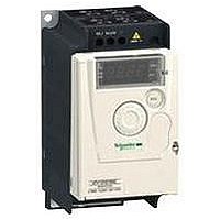
ATV12HU40M3
Manufacturer Part Number
ATV12HU40M3
Description
AC Drive
Manufacturer
SQUARE D
Specifications of ATV12HU40M3
No. Of Phases
Three
Power Rating
3.7kW
Output Voltage Max
230V
Output Current
16.7A
Supply Voltage Max
230V
Frequency Range
0.5 To 400Hz
Rohs Compliant
Yes
Lead Free Status / RoHS Status
Lead free / RoHS Compliant


Functions
Single variable mode
Single variable mode with auxiliary pump
HSP
Introduction:
page 8
FOF
Variable pump frequency (Hz)
FOn
Single variable mode with auxiliary pump: hysteresis
(continued)
2
Specifications:
page 10
Installation flow rate
1
3
3
1
2
Altivar
variable speed drives
The main objective here is to control a complete pumping installation using a single
Altivar
The Altivar 12 has 11 functions designed for water pumping applications:
b Control in single variable mode
b Control in single variable mode with auxiliary pump
b Underload detection
b Overload detection
b Sleep
b Wake-up
b PID feedback supervision
b No-load operation detection
b Quick start
b Automatic restart on underload and overload faults
b PID reference adjustment range for the end user
Control in single variable mode
The system is operated using a single variable speed pump (
A PID regulator controls the variable speed pump.
A pressure sensor provides the “PID feedback” information required for system
feedback.
Control in single variable mode with auxiliary pump
The system is operated using a fixed speed pump, called the auxiliary pump, and a
variable speed pump, which is unable to provide the full flow range required on its
own (
The auxiliary pump's starting and stopping are controlled by logic output LO+
according to the PID regulator output (variable pump frequency reference) with a
hysteresis effect as shown in the diagram below (
Auxiliary pump starting (
If the variable pump control frequency exceeds the threshold (FOn) for longer than a
time period (tON), the auxiliary pump is put into operation (1). The variable pump
reference decreases linearly until it reaches the threshold (FOF).
In order to reduce the effect of overpressure caused by starting of the auxiliary
pump, the deceleration time of the variable pump (rOn) must be set to the time that
the auxiliary pump takes to reach its nominal speed.
Auxiliary pump stopping (
Conversely, if the variable pump control frequency falls below the threshold (FOF)
for a period (tOF), the auxiliary pump is stopped (2) and the variable pump reference
increases linearly until it reaches the threshold (FOn). The acceleration time (rOF)
is set to the stopping time of the auxiliary pump in order to minimize the effect of
underpressure.
FOF
1
2
3
FOn: Starting frequency of the auxiliary pump
FOF: Stopping frequency of the auxiliary pump
References:
page 14
Variable pump frequency (Hz)
FOn
Auxiliary pump start
Pump-specific application functions
Auxiliary pump starting
Auxiliary pump stopping
Frequency range corresponding to the auxiliary pump flow rate
2
®
12 drive by ensuring constant pressure in the system whatever the flow rate.
).
®
tOn
12
rOn
1
4
5
)
Dimensions:
page 18
)
t
4
FOF
Auxiliary pump stop
Variable pump frequency (Hz)
FOn
3
).
tOF
2
Connections:
page 22
1
).
rOF
t
35
5
10
1
2
3
4
5
6
7
8
9
Related parts for ATV12HU40M3
Image
Part Number
Description
Manufacturer
Datasheet
Request
R


Part Number:
Description:
Pushbutton, Non-Illum'd Red "STOP", Momentary, 1NO-1NC, Square 30mm, 10A, 600V
Manufacturer:
SQUARE D
Datasheet:
Part Number:
Description:
CB ACCESSORY, UNDERVOLTAGE TRIP 48V DC
Manufacturer:
SQUARE D
Datasheet:
Part Number:
Description:
CB ACCESSORY, TRIP UNIT
Manufacturer:
SQUARE D
Datasheet: