V45450-1 VEEDER ROOT, V45450-1 Datasheet - Page 100
V45450-1
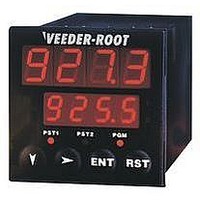
Manufacturer Part Number
V45450-1
Description
Multifunction Counter
Manufacturer
VEEDER ROOT
Type
Counterr
Specifications of V45450-1
No. Of Digits / Alpha
4
Digit Height
10mm
Counting Speed
10kHz
Operating Temperature Range
0°C To +55°C
Character Size
10mm
Panel Cutout Width
1.77"
Connection Type
Screw
Counter Type
Predetermining
Cut Out, Panel
1/16 DIN
Dimensions
1.89"L×4.33"W×1.89"H
Display Digit Height
10mm (Top Display), 7mm (Bottom Display)
Display Type
LED
Frequency, Operating
50⁄60 Hz
Function
Counter
Input Type
NPN
Mounting Type
Panel
Number Of Digits
6
Primary Type
Electronic
Standards
UL and cUL Recognized, CE Marked
Temperature, Operating, Range
0 to +50 °C
Terminal Type
Screw Terminal
Termination
Screw Terminal
Voltage, Supply
90 to 264 VAC
Weight
7 Oz.
Input Signals Accepted From A Variety Of Sources
Dry Contact, PNP or NPN Sensors, Encoders
Lead Free Status / RoHS Status
na


R
O
N
E
L
E
C
T
C
I
5
M
R
S
T
E
M
I
T
E
R
S
I
5.06
The Eagle Signal brand Series HP5E CYCL- FLEX timer is a modern,
microprocessor based reset timer housed in the standard CYCL- FLEX
plug-in enclosure. Timing progress is indicated by a LED array that
displays remaining time interval. Its 5.20 inches circumference
calibrated dial is easy-to-read with well defined resolution increments on
all ranges. The 15 terminal ABS (U. L. rated 94V- 0) molded housing
has high impact resistance and will not support combustion.
SPECIFICATIONS
Time Ranges
Reset Time: 500 mS at maximum setting
Voltage/ Frequency:
120 V (+10 -15%) 50/60 Hz
240 V (+10 -15%) 50/60 Hz
Power Consumption: 1.5 watts
Contact Rating:
10 Amps Resistive / Inductive @ 120vAC 1/6 HP @ 120VAC
5 Amps Resistive / Inductive @ 240VAC 1/2 HP @ 240VAC
Electrical Contact Lifetime: Average, contingent on load characteris-
tics. Inrush current should not exceed 10 amps.
At full load: 250,000 cycles
At 1 amp load: 5 million cycles
Sym.
16 standard time ranges from 5 seconds to 60 hours
Knob adjustable time ranges and LED progress indicator
Pilot light indicates when timer is active
Optional reverse action mode will not reset on power failure
15 terminal ABS (UL rated 94V-0) molded housing has high impact
resistance and will not support combustion
EAGLE SIGNAL
17
15
14
18
10
11
0
1
2
3
4
5
6
7
8
9
Electronic Timers
VEEDER-ROOT • EAGLE SIGNAL • DYNAPAR
150 Sec.
150 Min.
10 Sec.
15 Sec.
30 Sec.
60 Sec.
10 Min.
15 Min.
30 Min.
60 Min.
5 Sec.
5 Min.
10 Hr.
30 Hr.
60 Hr.
Dial
5 Hr.
Minimum
Setting
1/5 Sec.
1/5 Sec.
1/2 Sec.
12 Sec.
12 Min.
12 Min.
12 Sec
1 Sec.
1 Sec.
5 Sec.
1 Min.
1 Min.
1 Min.
5 Min.
1 Hr.
1 Hr.
Divisions
1/5 Sec.
1/5 Sec.
1/2 Sec.
12 Sec.
12 Sec.
12 Min.
12 Min.
1 Sec.
1 Sec.
5 Sec.
1 Min.
1 Min.
1 Min.
5 Min.
1 Hr.
Dial
1Hr.
brand
Accuracy
Repeat
.05 Sec.
.05 Sec.
.08 Sec.
1.5 Sec.
7.5 Sec.
4.5 Sec.
1.5 Min.
15 Sec.
18 Sec.
45 Sec.
18 Min.
3 Sec.
2 Sec.
9 Sec.
3 Min.
9 Min.
HP5E CYCL-FLEX
OPERATION (reference Schmatic Diagram)
Standard: Instantaneous contacts 9-10-C and 6-7-8 operates directly
with power applied to 1, 11(E) and 2. Different operating sequences are
possible depending on the control circuit configuration.
Delayed contacts 4- 3 and 11- A close and contacts 4- 5 and 11- 12
open when timer reaches a timed out condition. Contacts 4- 5 and 11-
12 close and contacts 4- 3 and 11- A open when timer is reset.
Reverse Start: Instantaneous contacts 9-10-C and 6-7-8 operates
directly with power applied to 1, 11(E) and 2. Different operating
sequences are possible depending on the control circuit configuration.
Delayed contacts 4- 3 and 11- A close and contacts 4- 5 and 11- 12
open when timer reaches a timed out position. Contacts 4- 5 and 11- 12
close and contacts 4- 3 and 11- A open when timer is reset.
Power On Response:
28 ms average pull-in
17 ms average drop-out
Operationg Temerature: -10 to +140 F (-23 to +60 C)
Approximate weight: 1.7 lbs.
Agency Approvals: FM; UL/CUL Recognition
Modern, high quality timer
housed in industry standard
patented plug-in housing
1
9
6
STANDARD
Factory Wiring
C
7
10
8
CRI
11
4
2
E
Schematic Diagram
5
12
A
3
®
File No. E61735
C
Reset Timer
®
US
E61735
CRI
1
9
6
REVERSE
Factory Wiring
C
7
10
8
A P P R O V E D
11
4
F M
2
E
5
12
A
3
Related parts for V45450-1
Image
Part Number
Description
Manufacturer
Datasheet
Request
R

Part Number:
Description:
Batch Counter
Manufacturer:
VEEDER ROOT
Datasheet:
Part Number:
Description:
Multifunction Counter
Manufacturer:
VEEDER ROOT
Datasheet:

Part Number:
Description:
Module; Veeder-Root Brand, A103 Series; NEMA Approved; 10 to 20 VDC
Manufacturer:
Veeder-Root
Datasheet:
Part Number:
Description:
Module; Veeder-Root Brand, A103 Series; NEMA Approved; 10 to 20 VDC
Manufacturer:
Veeder-Root
Datasheet:
Part Number:
Description:
COUNTER, VEEDER-ROOT, SQ. CASE, RAT. DR., FLANGE MOUNT, 5 FIGS., #2 ROT.
Manufacturer:
Veeder-Root
Datasheet:
Part Number:
Description:
HOUR METER, ROUND, 9-85VDC, BLADE TERMINALS, VEEDER-ROOT LOGO
Manufacturer:
Veeder-Root
Datasheet:
Part Number:
Description:
COUNTER, VEEDER-ROOT, RATCHET DRIVE, KNOB RESET, #3 ROT.
Manufacturer:
Veeder-Root
Datasheet:
Part Number:
Description:
MAX Count Series, 3 Solid State And 3 Relay Outputs
Manufacturer:
VEEDER ROOT

Part Number:
Description:
Encoder
Manufacturer:
VEEDER ROOT
Datasheet:
Part Number:
Description:
Inductive Proximity Sensor
Manufacturer:
VEEDER ROOT
Datasheet:
Part Number:
Description:
TIMER ACCESSORY, SOCKET
Manufacturer:
VEEDER ROOT
Datasheet:
Part Number:
Description:
Encoder, Bidirectional, Flange Mount
Manufacturer:
Veeder-Root
Datasheet: