CUB5VB00 Red Lion Controls, CUB5VB00 Datasheet - Page 6
CUB5VB00
Manufacturer Part Number
CUB5VB00
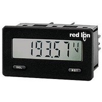
Description
Voltage Meter
Manufacturer
Red Lion Controls
Type
Voltager
Datasheet
1.CUB5VB00.pdf
(12 pages)
Specifications of CUB5VB00
No. Of Digits / Alpha
5
Meter Function
DC Voltmeter
Meter Range
0mV To 200mV / 0V To 2V / 0V To 20V / 0V To 200V
Digit Height
12.2mm
Operating Temperature Range
-35°C To +75°C
Meter Signal Input
Voltage
Accuracy
±0.1% %
Connection Type
Screw
Cut Out, Panel
2.68×1.3 "
Dimensions
2.95"L×1.86"W×1.54"H
Display Digit Height
0.48 "
Display Type
LCD
Function
Voltage
Material, Casing
Plastic
Number Of Digits
5
Primary Type
Electronic
Range, Measurement
200 mVDC to 200 VDC
Special Features
Communication and Control
Voltage, Supply
9 to 28 VDC
Power Supply
9 to 28 VDC
Dc Current
200 μA to 200 mA
Dc Voltage
200 mV to 200 V
Process Signals
0(4) to 20 mA or 0 - 10 VDC
Display Mode
Selectable Transmissive
Rohs Compliant
Yes
Backlighting Color
Red Or Green
Lead Free Status / RoHS Status
Lead free / RoHS Compliant


OPERATING MODE DISPLAY DESIGNATORS
the enabled display values.
PROGRAMMING MODE ENTRY (SEL BUTTON)
installation. The meter normally operates in the Display Mode. No parameters
can be programmed in this mode. The Programming Mode is entered by
pressing and holding the
either a security code, or a hardware lock.
MODULE ENTRY (SEL & RST BUTTONS)
group together parameters that are related in function. The display will alternate
between
module. The displayed module is entered by pressing the
MODULE MENU (SEL BUTTON)
module discussion). The
parameter to be changed, without changing the programming of preceding
parameters. After completing a module, the display will return to
Programming may continue by accessing additional modules.
SELECTION / VALUE ENTRY
the selections/value for that parameter. The
the selections/values for that parameter. Pressing the
activates the displayed selection/value. This also advances the meter to the next
parameter.
most digit will begin to flash. Pressing the
digit by one or the user can hold the
scroll. The
SEL
5.0 R
6.0 P
MAX - Maximum display capture value
MIN - Minimum display capture value
Pressing the
It is recommended all programming changes be made off line, or before
The Programming Menu is organized into separate modules. These modules
Each module has a separate module menu (which is shown at the start of each
For each parameter, the display alternates between the present parameter and
For numeric values, press the
button will enter the value and move to the next parameter.
BUTTON
Pro
SEL
RST
SEL
and the present module. The
SEL
button will advance to the next digit. Pressing and holding the
ROGRAMMING THE
button toggles the meter through the selected displays. If display scroll is enabled, the display will toggle automatically every four seconds between
EVIEWING THE
DISPLAY MODE OPERATION
Index display through enabled values
Resets values (MIN/MAX) or outputs
DISPLAY
SEL
SEL
MODE
Pro
NO
SEL
button. If it is not accessible then it is locked by
button is pressed to advance to a particular
RST
RST
button to access the value. The right hand
Signal Input
Parameters
1-INP
RST
RST
button and the digit will automatically
RST
button is used to select the desired
RST
SEL
button is used to move through
button again increments the
SEL
SEL
button, stores and
button.
PROGRAMMING MENU
Parameters
Secondary
ENTERING PROGRAM MODE
Press and hold for 2 seconds to activate
2-SEC
Function
F
SEL
SEL
Pro
OVERVIEW
RONT
NO
M
.
Display and Front
6
ETER
Parameters
Panel Key
3-dSP
PROGRAMMING MODE EXIT (SEL BUTTON)
displayed. This will commit any stored parameter changes to memory and
return the meter to the Display Mode. (If power loss occurs before returning to
the Display Mode, verify recent parameter changes.)
PROGRAMMING TIPS
sequence. When programming is complete, it is recommended to record the
parameter programming and lock out parameter programming with the user input
or programming security code.
FACTORY SETTINGS
when encountering programming problems.
ALTERNATING SELECTION DISPLAY
appear. This is used to illustrate the display alternating between the parameter
on top and the parameter’s Factory Setting on the bottom. In most cases,
selections and values for the parameter will be listed on the right.
“1” - To the right of the display indicates setpoint 1 output activated.
“2” - To the right of the display indicates setpoint 2 output activated.
The Programming Mode is exited by pressing the
It is recommended to start with Module 1 and proceed through each module in
Factory Settings may be completely restored in Module 2. This is useful
In the explanation of the modules, the following dual display with arrows will
B
SEL
UTTONS AND
RST
Parameter
Indicates Program Mode Alternating Display
PROGRAMMING MODE OPERATION
Store selected parameter and index to next parameter
Advances through the program menu
Increments selected parameter value or selection
Parameters
4-SPt
Setpoint
Output
Factory Settings are shown.
SEL
USrIN
N0
Parameters
5-SEr
Setup
Serial
D
Selection/Value
SEL
ISPLAY
SEL
button with
Pro NO
Related parts for CUB5VB00
Image
Part Number
Description
Manufacturer
Datasheet
Request
R

Part Number:
Description:
Counter
Manufacturer:
Red Lion Controls
Datasheet:
Part Number:
Description:
Miniature Length Sensor
Manufacturer:
Red Lion Controls
Datasheet:
Part Number:
Description:
Model Lsc - Single Channel Output Length Sensor
Manufacturer:
Red Lion Controls
Datasheet: