GT3F-2AD24 IDEC, GT3F-2AD24 Datasheet - Page 9
GT3F-2AD24
Manufacturer Part Number
GT3F-2AD24
Description
Electromechanical General Purpose Timer
Manufacturer
IDEC
Type
Off Delayr
Datasheet
1.GT3A-4AD24.pdf
(41 pages)
Specifications of GT3F-2AD24
Leaded Process Compatible
No
No. Of Pins
8
Peak Reflow Compatible (260 C)
No
Switch Function
DPDT
Supply Voltage
250VAC
Time Range Min
0.05s
Supply Current
5A
Time Range Max
600s
Rohs Compliant
No
Lead Free Status / RoHS Status
Contains lead / RoHS non-compliant


G
GT3A Series
G-22
Select the desired mode
of operation.
Select the time range
that contains the desired
time period.
Set the precise period of time desired by using the
Step 1.
Step 2.
Step 3.
www.idec.com
Timed OUT Indicator
Selector
A, B, C, D
Operation Mode
GT3A-1
GT3A-2
GT3A-3
GT3A-4
GT3A-5
GT3A-6
0.05 seconds to 1 second
0.05 seconds to 3 seconds
0.05 seconds to 6 seconds
0.15 seconds to 18 seconds
0.1 seconds to 10 seconds
0.3 seconds to 30 seconds
0.6 seconds to 60 seconds
1.8 seconds to 180 seconds
6 seconds to 10 minutes
18 seconds to 30 minutes
36 seconds to 60 minutes
108 seconds to 180 minutes
6 minutes to 10 hours
18 minutes to 30 hours
36 minutes to 60 hours
108 minutes to 180 hours
For Timers
Desired Mode of Operation
Desired Time Range
Time Ranges
ON-delay 1
Interval 1
Cycle 1
Cycle 3
ON-delay 2
Cycle 2
Signal ON/OFF-delay 1
Signal OFF-delay 1
Interval 2
One-shot cycle
Signal ON/OFF-delay 2
Signal OFF-delay 2
One-shot 1
One-shot ON-delay
One-shot 2
Signal ON/OFF-delay 3
Mode of Operation
Instructions: Setting GT3A Series Timers
Setting Knob.
0-1, 0-3, 0-6, 0-18
Dial Selector
Selection
USA: (800) 262-IDEC or (408) 747-0550, Canada: (888) 317-IDEC
A
B
C
D
A
B
C
D
A
B
C
D
A
B
C
D
0-1
0-3
0-6
0-18
0-1
0-3
0-6
0-18
0-1
0-3
0-6
0-18
0-1
0-3
0-6
0-18
Dial Selector
Operation Mode Selector
Selection
Selection
1S
10S
10M
10H
Time Range Selector
1S, 10S, 10M, 10H
Time Range Selector
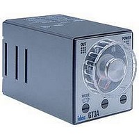
POWER Indicator
(flashes during
time-delay period)
Setting Knob
Timers
The desired operation mode
can be selected from the A, B,
C, and D modes using the Oper-
ation Mode Selector. Change
the operation mode from A to
B, C, and D in turn by turning
the operation mode selector
clockwise using a flat screw-
driver which is a maximum of
0.156” (4mm) wide. The
selected mode is displayed
in the window.
The desired time range is
selected by setting both
Dial Selector and
Time Range Selector.
Remarks
Remarks
A
Related parts for GT3F-2AD24
Image
Part Number
Description
Manufacturer
Datasheet
Request
R

Part Number:
Description:
GT3F-1AD24 8PIN DPDT TRUE POWER OFF DELAY TIMER
Manufacturer:
IDEC
Datasheet:
Part Number:
Description:
GT3F-1EAF20 11 PIN SPDT TRUE POWER OFF DELAY TIMER
Manufacturer:
IDEC
Datasheet:
Part Number:
Description:
GT3F-2EAF20 11 PIN DPDT TRUE POWER OFF DELAY TIMER
Manufacturer:
IDEC
Datasheet:
Part Number:
Description:
Relay; E-Mech; Timing; Off Delay; DPDT; Cur-Rtg 3A; Ctrl-V 100-240AC; Socket Mnt; Screw
Manufacturer:
IDEC Corporation
Datasheet:
Part Number:
Description:
Cable; Between IDEC MicroSmart (port 1 or 2) and HG2F/3F/4F; 5 ft.
Manufacturer:
IDEC Corporation
Datasheet:
Part Number:
Description:
Cable; Between IDEC Micro^3C/ONC/MicroSmart (port 2) PLCs and HG2F/3F/4F; 5 ft.
Manufacturer:
IDEC Corporation
Datasheet:
Part Number:
Description:
Angled Key for Idec HS6B Safety Switch
Manufacturer:
IDEC Corporation
Datasheet:
Part Number:
Description:
Accessory, L-Shaped Key for Idec HS5B and HS5E Safety Switch
Manufacturer:
IDEC Corporation
Datasheet:
Part Number:
Description:
Accessory, Straight Key for Idec HS5B and HS5E Safety Switch
Manufacturer:
IDEC Corporation
Datasheet:
Part Number:
Description:
Straight Key for Idec HS6B Safety Switch
Manufacturer:
IDEC Corporation
Datasheet:
Part Number:
Description:
Antenna/ Sensor/ and Communications Trunk Line Connections
Manufacturer:
Hirose Electric
Datasheet:
Part Number:
Description:
Interface Portions and In-line Portions of the Various Units and Devices
Manufacturer:
Hirose Electric
Datasheet:
Part Number:
Description:
Antenna, Sensor, and Communications Trunk Line Connections
Manufacturer:
HIROSE [Hirose Electric]
Datasheet:
Part Number:
Description:
INDICATOR INCANDESCENT LAMP, GREEN
Manufacturer:
IDEC
Datasheet:

Part Number:
Description:
LAMP, INDICATOR, INCAND, AMB
Manufacturer:
IDEC
Datasheet: