IFMR0036 Red Lion Controls, IFMR0036 Datasheet - Page 3
IFMR0036
Manufacturer Part Number
IFMR0036
Description
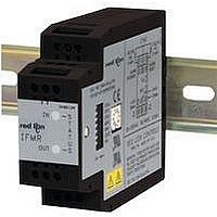
Isolation Amplifier
Manufacturer
Red Lion Controls
Type
Speedr
Specifications of IFMR0036
Width
3.12"
Signal Input Type
Selectable Current Or Voltage
Configuration Setup
DIP Switch
Supply Voltage Max
32VDC
Iso-amp Mounting Type
DIN Rail
Display Alarm Type
Relay
Input Accuracy
± 0.1% Of FS
Application
The IFMR utilizes a seven position DIP switch, a rotary switch, a pushbutton and two indication LEDs to accomplish input circuit configuration, operational parameter set-up, input signal, and relay status indication
Brand/series
IFMR Series
Contact Form
SPDT
Current Rating
5 A
Dimensions
27.5mmW×4.2mmH×79.2mmD
Display Type
LED
Input Type
Analog
Mounting Type
DIN Rail
Output Type
Relay
Power, Rating
2 W
Primary Type
Controller
Sensor, Input
12 VDC
Standards
cURus, CE
Temperature, Operating
0 to +50 °C
Termination
Screw
Voltage, Rating
9 to 32 VDC
Voltage, Supply
9-32 VDC
Signal Output Type
Current
Rohs Compliant
Yes
Lead Free Status / RoHS Status
Lead free / RoHS Compliant
For Use With
Sensors/Switches/TTL


OVERVIEW
output relay based on the frequency of the input signal, the chosen Operation
Mode (Underspeed or Overspeed), and the Trip and Release points the user has
selected. The green Input LED blinks at the rate of the input frequency. At about
100 Hz, the Input LED will appear to be solid on. At very low frequencies, the
Input LED blinks slowly and may also appear to be solid on. A loss of signal
may also cause the Input LED to remain on, depending on the DIP switch set-
up. In this case, the red Relay LED also turns on. The IFMR indicates the status
of the relay with the Relay LED (Red). Whenever the relay is in the Trip state,
the IFMR turns ON the Relay LED. In the Release state, the Relay LED is OFF.
Minimum Response Time) exceeds the Trip point, the IFMR trips the relay.
With the relay in the Trip condition, the input frequency must fall below the
Release point for the relay to release.
over the Minimum Response Time) falls below the Trip point. The relay
releases only after the input frequency has exceeded the Release point. Two of
the Underspeed operating modes allow the machine or system that supplies the
input signal to reach normal operating speed before the IFMR responds to an
Underspeed condition. For Zero Speed applications, bear in mind that Zero
Speed detection and Underspeed detection are identical.
the output. The actual response time is the Minimum Response Time plus up to
one full period of the input signal. The IFMR counts the negative edges
occurring during the update time period, and computes the average frequency
value for that time. This action filters out any high frequency jitter that may be
present in the input signal. The longer the Minimum Response Time, the more
filtering occurs.
for Overspeed operation. For Underspeed operation the Trip point becomes the
Trip Frequency minus the Offset value.
which can lead to cycling or “chattering” of the relay at input frequencies
hovering around the Trip point. If Hysteresis is selected, the Release point is set
to the Trip point (including Offset) minus the Hysteresis value for Overspeed
detection. For Underspeed detection, the Release point is set to the Trip point
(including Offset) plus the Hysteresis value.
optional connection of push-buttons. The Alarm Override pin causes the IFMR
to unconditionally Release the relay, regardless of the input frequency, or the
state of the relay, when pulled to common. When the Alarm Override pin is
released from common, the operation of the IFMR returns to normal, and the
status of the relay is updated based on the input frequency.
operation modes. With the Latch function selected, the relay “latches” into the
Trip state whenever a Trip condition is detected. The relay remains latched until
the Alarm Reset pin is pulled to common while the input frequency is in the
Release region. The Alarm Reset pin is ignored while the input frequency is in
the Trip region.
EMC INSTALLATION GUIDELINES
Interference (EMI), proper installation and wiring methods must be followed to
ensure compatibility in each application. The type of the electrical noise, source
or coupling method into the unit may be different for various installations. The
unit becomes more immune to EMI with fewer I/O connections. Cable length,
routing, and shield termination are very important and can mean the difference
between a successful installation or a troublesome installation.
industrial environment.
1. Use shielded (screened) cables for all Signal and Control inputs. The shield
The Model IFMR continuously monitors the input signal and controls an
For Overspeed detection, when the input frequency (averaged over the
For Underspeed detection, the relay trips when the input frequency (averaged
The Minimum Response Time parameter sets the minimum update time of
The Offset value is added to the Trip Frequency to determine the Trip Point
If No Hysteresis has been selected, the Trip and Release points are identical,
Two input pins (Alarm Override and Alarm Reset) are provided for the
The Alarm Reset pin is only active when the IFMR is in one of the Latch
Although this unit is designed with a high degree of immunity to ElectroMagnetic
Listed below are some EMC guidelines for successful installation in an
(screen) pigtail connection should be made as short as possible. The
connection point for the shield depends somewhat upon the application.
3
2. Never run Signal or Control cables in the same conduit or raceway with AC
3. Signal or Control cables within an enclosure should be routed as far away as
4. In very electrically noisy environments, the use of external EMI suppression
5. Long cable runs are more susceptible to EMI pickup than short cable runs.
WIRING CONNECTIONS
Also cabling should conform to appropriate standards of good installation, local
codes and regulations. It is recommended that power supplied to the unit (AC
or DC) be protected by a fuse or circuit breaker.
POWER AND OUTPUT CONNECTIONS
AC Power
results, the AC Power should be relatively “clean” and within the specified
variation limits. Drawing power from heavily loaded circuits or from circuits
that also power loads that cycle on and off, should be avoided.
DC Power
Terminals 10 and 12. The DC plus (+)
is connected to Terminal 10 and the
minus (-) is connected to Terminal 12.
It is recommended that separate
supplies be used for sensor power and
unit power. Using the same supply for
both will negate isolation between
input and power.
Output Wiring
connect to the relay output. Terminal 1
is the normally open contact. Terminal
3 is the normally closed contact, and
Terminal 2 is the output relay common.
Listed below are the recommended methods of connecting the shield, in
a. Connect the shield only at the rail where the unit is mounted to earth
b. Connect the shield to earth ground at both ends of the cable, usually when
c. Connect the shield to common of the unit and leave the other end of the
power lines, conductors feeding motors, solenoids, SCR controls, and
heaters, etc. The cables should be run in metal conduit that is properly
grounded. This is especially useful in applications where cable runs are long
and portable two-way radios are used in close proximity or if the installation
is near a commercial radio transmitter.
possible from contactors, control relays, transformers, and other noisy
components.
devices, such as ferrite suppression cores, is effective. Install them on Signal
and Control cables as close to the unit as possible. Loop the cable through the
core several times or use multiple cores on each cable for additional protection.
Install line filters on the power input cable to the unit to suppress power line
interference. Install them near the power entry point of the enclosure. The
following EMI suppression devices (or equivalent) are recommended:
Therefore, keep cable runs as short as possible.
All conductors should meet voltage and current ratings for each terminal.
Primary power is connected to terminals 10 and 12 (labeled AC). For best
The DC power is connected to
Terminals 1, 2, and 3 are used to
order of their effectiveness.
ground (protective earth).
the noise source frequency is above 1 MHz.
shield unconnected and insulated from earth ground.
Ferrite Suppression Cores for signal and control cables:
Line Filters for input power cables:
Note: Reference manufacturer’s instructions when installing a line filter.
Fair-Rite # 0443167251 (RLC #FCOR0000)
TDK # ZCAT3035-1330A
Steward #28B2029-0A0
Schaffner # FN610-1/07 (RLC #LFIL0000)
Schaffner # FN670-1.8/07
Corcom #1VR3
120/240
5 AMP
OVERRIDE
VAC
ALARM
60mA
+12V
~
AC
10
4
7
1
OUT
11
2
5
8
IN
12
6
3
9
ALARM
RESET
~
AC
120/240
5 AMP
INPUT
COMM
VAC
Related parts for IFMR0036
Image
Part Number
Description
Manufacturer
Datasheet
Request
R

Part Number:
Description:
Counter
Manufacturer:
Red Lion Controls
Datasheet:
Part Number:
Description:
Miniature Length Sensor
Manufacturer:
Red Lion Controls
Datasheet:
Part Number:
Description:
Model Lsc - Single Channel Output Length Sensor
Manufacturer:
Red Lion Controls
Datasheet: