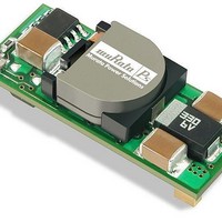
LSM-0.8/10-D12-C Murata Power Solutions Inc, LSM-0.8/10-D12-C Datasheet - Page 5

LSM-0.8/10-D12-C
Manufacturer Part Number
LSM-0.8/10-D12-C
Description
DC/DC SM 10A 12-0.8V Non-Iso
Manufacturer
Murata Power Solutions Inc
Series
LSMr
Datasheet
1.LSM-510-D12-C.pdf
(18 pages)
Specifications of LSM-0.8/10-D12-C
Product
Non-Isolated / POL
Output Power
8 W
Input Voltage Range
10.8 V to 13.2 V
Input Voltage (nominal)
12 V
Number Of Outputs
1
Output Voltage (channel 1)
0.8 V
Output Current (channel 1)
10 A
Output Type
Low Voltage
Lead Free Status / Rohs Status
Lead free / RoHS Compliant
PARD) may be reduced below specified limits with the installation of additional
external output capacitors. Output capacitors function as true filter elements
and should be selected for bulk capacitance, low ESR, and appropriate fre-
quency response. Any scope measurements of PARD should be made directly
at the DC/DC output pins with scope probe ground less than 0.5" in length.
located as close to the converters as possible. Temperature variations for all
relevant parameters should be taken into consideration.
tion of your line voltage and source impedance, as well as your particular load
and layout conditions. Our Applications Engineers can recommend potential
solutions and discuss the possibility of our modifying a given device’s internal
filtering to meet your specific requirements. Contact our Applications Engineer-
ing Group for additional details.
Input Fusing
Most applications and or safety agencies require the installation of fuses at
the inputs of power conversion components. LSM D12 Series DC/DC convert-
Output ripple/noise (also referred to as periodic and random deviations or
All external capacitors should have appropriate voltage ratings and be
The most effective combination of external I/O capacitors will be a func-
COMMON
+OUTPUT
+SENSE
Figure 3. Measuring Output Ripple/Noise (PARD)
Figure 2. Measuring Input Ripple Current
C1 = NA
C2 = 22μF TANTALUM
LOAD 2-3 INCHES (51-76mm) FROM MODULE
6
4
3
C1
COPPER STRIP
COPPER STRIP
C2
www.murata-ps.com
SCOPE
R
LOAD
ers are not internally fused. Therefore, if input fusing is mandatory, either a
normal-blow or a fast-blow fuse with a value no greater than 20 Amps should
be installed within the ungrounded input path to the converter.
slow-blow fuse with a typical value of about twice the maximum input current,
calculated at low line with the converters minimum efficiency.
Safety Considerations
LSM D12 SMT's are non-isolated DC/DC converters. In general, all DC/DC's
must be installed, including considerations for I/O voltages and spacing/sepa-
ration requirements, in compliance with relevant safety-agency specifications
(usually UL/IEC/EN60950-1).
(safety extra low voltage) requirements, its input must be SELV compliant. If the
output needs to be ELV (extra low voltage), the input must be ELV.
Input Overvoltage and Reverse-Polarity Protection
LSM D12 SMT Series DC/DCs do not incorporate either input overvoltage or
input reverse-polarity protection. Input voltages in excess of the specified
absolute maximum ratings and input polarity reversals of longer than "instan-
taneous" duration can cause permanent damage to these devices.
Start-Up Time
The V
ing input voltage crosses the lower limit of the specified input voltage range
and the fully loaded output voltage enters and remains within its specified
accuracy band. Actual measured times will vary with input source impedance,
external input capacitance, and the slew rate and final value of the input volt-
age as it appears to the converter.
On/Off Control with the nominal input voltage already applied to the converter.
The specification defines the interval between the time at which the converter
is turned on and the fully loaded output voltage enters and remains within its
specified accuracy band. See Typical Performance Curves.
Remote Sense
LSM D12 SMT Series DC/DC converters offer an output sense function on pin 6.
The sense function enables point-of-use regulation for overcoming moderate
IR drops in conductors and/or cabling. Since these are non-isolated devices
whose inputs and outputs usually share the same ground plane, sense is
provided only for the +Output.
converter’s output. The sense line carries very little current and consequently
requires a minimal cross-sectional-area conductor. As such, it is not a low-
impedance point and must be treated with care in layout and cabling. Sense
lines should be run adjacent to signals (preferably ground), and in cable and/or
discrete-wiring applications, twisted-pair or similar techniques should be used.
To prevent high frequency voltage differences between V
recommend installation of a 1000pF capacitor close to the converter.
As a rule of thumb however, we recommend to use a normal-blow or
In particular, for a non-isolated converter's output voltage to meet SELV
The On/Off to V
The remote sense line is part of the feedback control loop regulating the
IN
Non-Isolated, 12V
to V
OUT
Start-Up Time is the interval between the time at which a ramp-
OUT
Technical enquiries email: sales@murata-ps.com, tel:
Start-Up Time assumes the converter is turned off via the
IN
LSM-10A D12 Models
, 0.75-5V
MDC_LSM 10A D12 Models.B01 Page 5 of 18
Single Output
OUT
DC/DC Converters
OUT
and Sense, we
+1 508 339 3000


