LSM-0.8/10-D12-C Murata Power Solutions Inc, LSM-0.8/10-D12-C Datasheet - Page 8
LSM-0.8/10-D12-C
Manufacturer Part Number
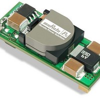
LSM-0.8/10-D12-C
Description
DC/DC SM 10A 12-0.8V Non-Iso
Manufacturer
Murata Power Solutions Inc
Series
LSMr
Datasheet
1.LSM-510-D12-C.pdf
(18 pages)
Specifications of LSM-0.8/10-D12-C
Product
Non-Isolated / POL
Output Power
8 W
Input Voltage Range
10.8 V to 13.2 V
Input Voltage (nominal)
12 V
Number Of Outputs
1
Output Voltage (channel 1)
0.8 V
Output Current (channel 1)
10 A
Output Type
Low Voltage
Lead Free Status / Rohs Status
Lead free / RoHS Compliant


Voltage Trim
The LSM-T/10-D12 may also be trimmed using an external voltage applied
between the Trim input and Output Common. Be aware that the internal “load”
impedance looking into trim pin is approximately 5kΩ. Therefore, you may have to
compensate for this in the source resistance of your external voltage reference.
Output Reverse Conduction
Many DC/DCs using synchronous rectification suffer from Output Reverse
Conduction. If those devices have a voltage applied across their output before
a voltage is applied to their input (this typically occurs when another power
supply starts before them in a power-sequenced application), they will either
fail to start or self destruct. In both cases, the cause is the "freewheeling" or
"catch" FET biasing itself on and effectively becoming a short circuit.
tion. They employ proprietary gate drive circuitry that makes them immune to
applied output voltages.
Thermal Considerations and Thermal Protection
The typical output-current thermal-derating curves shown below enable
designers to determine how much current they can reliably derive from each
model of the LSM D12 SMT's under known ambient-temperature and air-flow
conditions. Similarly, the curves indicate how much air flow is required to reli-
ably deliver a specific output current at known temperatures.
(typ.)
(typ.)
R
(k )
V
V
V
The resistor trim up equation for the LSM-T/10-D12 is as follows:
Where V
The LSM-T/10-D12 fixed resistance values to set the output values are:
CAUTION: To retain proper regulation, do not exceed the 5 Volt output.
The equation for this voltage adjustment is:
The LSM-T/10-D12 fixed trim voltages to set the output voltage are:
LSM D12 SMT DC/DC converters do not suffer from Output Reverse Conduc-
OUT
TRIM
OUT
TRIM
0.7525
0.7525
Open
Open 0.68354 0.67
V
O
TRIM
is the desired output voltage.
= 0.7 –(0.0667 x (V
41.424 22.46
R
1.0
1.0
TRIM UP
( ) =
1.2
1.2
13.05
V
0.65
1.5
1.5
O
O
10500
– 0.7525
– 0.7525))
9.024
0.63
1.8
1.8
–1000
7.417
0.617
www.murata-ps.com
2
2
5.009
0.583
2.5
2.5
3.122
0.53
3.3
3.3
0.4166
1.472
5.0
5.0
whose heat is generated primarily by I
developed using thermocouples to monitor the inductor temperature and vary-
ing the load to keep that temperature below +110°C under the assorted condi-
tions of air flow and air temperature. Once the temperature exceeds +115°C
(approx.), the thermal protection will disable the converter. Automatic restart
occurs after the temperature has dropped below +110°C.
mately +115°C.
curves on the following pages, LSM D12 SMT's maintain virtually constant
efficiency from half to full load, and consequently deliver very impressive
temperature performance even if operating at full load.
obviously subject to numerous factors and tolerances not taken into account
here. If you are attempting to extract the most current out of these units under
demanding temperature conditions, we advise you to monitor the output-
inductor temperature to ensure it remains below +110°C at all times.
Start Up Considerations
When power is first applied to the DC/DC converter, operation is different than
when the converter is running and stabilized. There is some risk of start up
difficulties if you do not observe several application features. Lower input volt-
age converters may have more problems here since they tend to have higher
input currents. Operation is most critical with any combination of the following
external factors:
start up surge current may instantaneously reduce the voltage at the input
terminals to below the specified minimum voltage. Even if this voltage depres-
sion is very brief, this may interfere with the on-board controller and possibly
cause a failed start. Or the converter may start but the input current load will
now drive the input voltage below its running low limit and the converter will
shut down.
The highest temperatures in LSM D12 SMT's occur at their output inductor,
LSM-T/10-D12 thermal protection occurs at +125°C and restart at approxi-
As you may deduce from the derating curves and observe in the efficiency
Lastly, when LSM D12 SMT's are installed in system boards, they are
If the input voltage is already at the low limit before power is applied, the
1 - Low initial input line voltage and/or poor regulation of the input source.
2 – Full output load current on lower output voltage converters.
3 – Slow slew rate of input voltage.
4 – Longer distance to input voltage source and/or higher external input
5 - Limited or insufficient ground plane. External wiring that is too small.
6 – Too small external input capacitance. Too high ESR.
7 – High output capacitance causing a start up charge overcurrent surge.
8 – Output loads with excessive inductive reactance or constant current
Non-Isolated, 12V
source impedance.
characteristics.
Technical enquiries email: sales@murata-ps.com, tel:
IN
LSM-10A D12 Models
, 0.75-5V
MDC_LSM 10A D12 Models.B01 Page 8 of 18
2
R losses. The derating curves were
Single Output
OUT
DC/DC Converters
+1 508 339 3000
Related parts for LSM-0.8/10-D12-C
Image
Part Number
Description
Manufacturer
Datasheet
Request
R

Part Number:
Description:
DC/DC SM 10A 3-0.8V Non-Iso
Manufacturer:
Murata Power Solutions Inc
Datasheet:
Part Number:
Description:
DC/DC SM 10A 5-0.8V Non-Iso
Manufacturer:
Murata Power Solutions Inc
Datasheet:

Part Number:
Description:
Non-isolated, 12vin, 0.75-5vo U T Dc/dc Converters
Manufacturer:
C&D Technologies.
Datasheet:
Part Number:
Description:
Single Output, Non-isolated, 3.3vin, 0.8-2.5vo U T
Manufacturer:
C&D Technologies.
Datasheet:
Part Number:
Description:
Single Output, Non-Isolated, 3.3VIN, 0.8-2.5VOUT 10 Amp DC/DC�s in SMT Packages
Manufacturer:
MURATA [Murata Manufacturing Co., Ltd.]
Datasheet:

Part Number:
Description:
POWER OVER ETHERNET MODULE
Manufacturer:
Murata Power Solutions Inc
Datasheet:

Part Number:
Description:
POWER OVER ETHERNET MODULE
Manufacturer:
Murata Power Solutions Inc
Datasheet:

Part Number:
Description:
POWER OVER ETHERNET MODULE
Manufacturer:
Murata Power Solutions Inc
Datasheet:

Part Number:
Description:
POWER OVER ETHERNET MODULE
Manufacturer:
Murata Power Solutions Inc
Datasheet:

Part Number:
Description:
Power Inductors 2.2mH1.4A
Manufacturer:
Murata Power Solutions Inc
Datasheet:

Part Number:
Description:
DC/DC Converter
Manufacturer:
Murata Power Solutions Inc
Datasheet:

Part Number:
Description:
Transformers 5Vin 5Vout 200mA 4000Vdc 1:1.33 turn
Manufacturer:
Murata Power Solutions Inc
Datasheet:

Part Number:
Description:
POWER SUPPLY
Manufacturer:
Murata Power Solutions Inc
Datasheet:

Part Number:
Description:
DPM LED MINI 2VDC 3.5DIG LP RED
Manufacturer:
Murata Power Solutions Inc
Datasheet:

Part Number:
Description:
CONV DC/DC 1W 5VIN 5VOUT SIP SGL
Manufacturer:
Murata Power Solutions Inc
Datasheet: