ULQ-3.3/20-D48N-C Murata Power Solutions Inc, ULQ-3.3/20-D48N-C Datasheet
ULQ-3.3/20-D48N-C
Specifications of ULQ-3.3/20-D48N-C


Related parts for ULQ-3.3/20-D48N-C


ULQ-3.3/20-D48N-C Summary of contents
Page 1
... You can also "pick-and- place" the ULQ-SMT version optimizing your automated SMT process. From an 18-36V or 36-75V input, ULQ's deliver outputs of 1.2, 1.5, 1. fully rated 25A, 2 20A 15A and 12V at 8-10A. They employ an interleaved, synchronous-rectifi ...
Page 2
... ULQ-2/15-D48N ULQ-2/25-D24P ULQ-2/25-D48N ULQ-2.5/15-D48N-C 2.5 15 ULQ-3.3/15-D48N-C 3.3 15 ULQ-3.3/20-D24P-C 3.3 20 ULQ-3.3/20-D48N-C 3.3 20 ULQ-5/15-D24P ULQ-5/15-D48N ULQ-12/8-D24P ULQ-12/10-D48N ➀ Typical +25°C under nominal line voltage and full-load conditions. All models are A specifi ed with an external 1μF multi-layer ceramic and 10μF capacitors across their output pins. ...
Page 3
... See Output Trimming for detailed trim equations. The Current-Limit Inception point is the output current level at which the ULQ’s power-limiting (10) circuitry drops the output voltage 2% from its initial value. See Output Current Limiting and Short-Circuit Protection for more details ...
Page 4
... The ULQ Series implements a soft start circuit to limit the duty cycle of its PWM controller at power up, thereby limiting the input inrush current. ...
Page 5
... Nevertheless, if the sense function is not used for remote regulation the user should connect the +Sense to +V DC/DC converter pins. ULQ series converters employ a sense feature to provide point of use regula- tion, thereby overcoming moderate IR drops in pcb conductors or cabling. The remote sense lines carry very little current and therefore require minimal cross-sectional-area conductors ...
Page 6
... OUT OUT Trimming Output Voltage ULQ converters have a trim capability (pin 6) that enables users to adjust the output voltage from +10% to –20% (refer to the trim equations and trim graphs that follow). Adjustments to the output voltage can be accomplished via a trim pot (Figure single fi xed resistor as shown in Figures 6 and 7. ...
Page 7
... ULQ Models Single Output, Low-Profi le, Quarter-Brick 8-25 Amp Isolated DC/DC Converters Model ULQ-2 INCREASE (%) OUT Model ULQ-3 INCREASE (%) OUT in Output Voltage Model ULQ-1.5 Model ULQ-1.8 Model ULQ-2 Model ULQ-2.5 Model ULQ-3 DECREASE (%) OUT email: sales@murata-ps.com 21 Feb 2011 MDC_ULQ-15A.B03 Page ...
Page 8
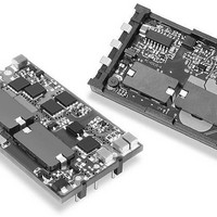
... Figure 8. Driving the Positive Polarity On/Off Control Pin Surface-Mount Package ("M" suffi x) DATEL's ULQ series SMT DC/DC converters are the only higher-power (to 66W) DC/DC's that can be automatically "pick-and-placed" using standard vacuum-pickup equipment and subsequently refl owed using high-tempera- ture, lead-free solder. ...
Page 9
... Input pin to Output pin – 22.5 25 www.murata-ps.com ULQ Models 8-25 Amp Isolated DC/DC Converters V = 18V 24V 36V Ambient Temperature (° 36V 48V 75V Ambient Temperature (°C) 0 lfm 100 lfm 200 lfm Ambient Temperature (°C) email: sales@murata-ps.com 21 Feb 2011 MDC_ULQ-15A.B03 Page 100 95 100 95 100 ...
Page 10
... Input pin to Output pin – www.murata-ps.com ULQ Models 8-25 Amp Isolated DC/DC Converters V = 36V 48V 75V Ambient Temperature (° 18V 24V 36V Ambient Temperature (°C) 0 lfm 100 lfm 200 lfm Ambient Temperature (°C) email: sales@murata-ps.com 21 Feb 2011 MDC_ULQ-15A.B03 Page 100 95 100 95 100 ...
Page 11
... Input pin to Output pin – 22.5 25 www.murata-ps.com ULQ Models 8-25 Amp Isolated DC/DC Converters V = 36V 48V 75V Ambient Temperature (° 18V 24V 36V Ambient Temperature (°C) 0 lfm 100 lfm 200 lfm Ambient Temperature (°C) email: sales@murata-ps.com 21 Feb 2011 MDC_ULQ-15A.B03 Page 100 95 100 86 90 ...
Page 12
... ULQ Models 8-25 Amp Isolated DC/DC Converters Natural Convection 100 lfm 200 lfm 300 lfm 400 lfm Ambient Temperature (°C) 100 lfm 200 lfm 300 lfm 400 lfm Ambient Temperature (°C) email: sales@murata-ps.com 21 Feb 2011 MDC_ULQ-15A.B03 Page 100 95 100 ...
Page 13
... Natural Convection 100 lfm 200 lfm 300 lfm 400 lfm Ambient Temperature (°C) 0 lfm 100 lfm 200 lfm 400 lfm Ambient Temperature (°C) 100 lfm 200 lfm 300 lfm Ambient Temperature (°C) email: sales@murata-ps.com 21 Feb 2011 MDC_ULQ-15A.B03 Page 100 100 100 ...
Page 14
... Typical Performance Curves, 5V Models www.murata-ps.com ULQ Models Single Output, Low-Profi le, Quarter-Brick 8-25 Amp Isolated DC/DC Converters email: sales@murata-ps.com 21 Feb 2011 MDC_ULQ-15A.B03 Page ...
Page 15
... ULQ Models Single Output, Low-Profi le, Quarter-Brick 8-25 Amp Isolated DC/DC Converters = 48V, air flow direction from Input pin to Output pin) 100 lfm 200 lfm 300 lfm Ambient Temperature (°C) email: sales@murata-ps.com 21 Feb 2011 MDC_ULQ-15A.B03 Page 500 lfm ...
Page 16
... For the surface mount versions of the ULQ, use the Recommended SMT Pad Layout illustration as a starting point to locate pads to mount the converter. This diagram is for the pads on the mating printed circuit board—it is not the dimensions of the lead terminals on the converter. Note: the pads are slightly larger than the lead terminals to accomodate solder wetting and meniscus ...