ULQ-3.3/20-D48N-C Murata Power Solutions Inc, ULQ-3.3/20-D48N-C Datasheet - Page 3
ULQ-3.3/20-D48N-C
Manufacturer Part Number
ULQ-3.3/20-D48N-C
Description
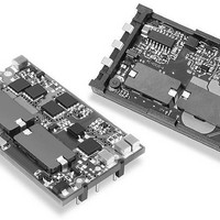
DC/DC TH 20A 48-3.3V Q-Brick
Manufacturer
Murata Power Solutions Inc
Series
ULQr
Datasheet
1.ULQ-1210-D48PM-C.pdf
(16 pages)
Specifications of ULQ-3.3/20-D48N-C
Product
Isolated
Output Power
66 W
Input Voltage Range
36 V to 75 V
Input Voltage (nominal)
48 V
Number Of Outputs
1
Output Voltage (channel 1)
3.3 V
Output Current (channel 1)
20 A
Isolation Voltage
2.25 KV
Package / Case Size
Quarter Brick
Lead Free Status / Rohs Status
Lead free / RoHS Compliant


Performance/Functional Specifi cations
Typical @ T
Input Voltage Range:
Overvoltage Shutdown
Start-Up Threshold:
Undervoltage Shutdown:
Input Current:
Input Refl ected Ripple Current
Internal Input Filter Type
Reverse-Polarity Protection
Remote On/Off Control (Pin 2):
Minimum Loading
V
V
Remote Sense Compensation
Ripple/Noise (20MHz BW)
Line/Load Regulation
Effi ciency
Isolation Voltage: Input-to-Output
Isolation Resistance
Isolation Capacitance
Current Limit Inception (98% V
Short Circuit:
Overvoltage Protection:
Dynamic Load Response
Start-Up Time:
Switching Frequency
Maximum Capacitive Load
OUT
OUT
D24 Models
D48 Models
D24 Models
D48 Models
D24 Models
D48 Models
D24 Models
D48 Models
Normal Operating Conditions
Inrush Transient
Short Circuit
Standby Mode:
Positive Logic ("P" Suffi x Models)
Negative Logic ("N" Suffi x Models)
Initial
Temperature Coeffi cient
Extreme
After warmup
Current
Duration
OVP method
(50% Load Step)
V
IN
Off, UV, Thermal Shutdown
Trim Range
Accuracy (Full Load):
to V
A
= +25°C under nominal line voltage, full-load conditions, unless noted.
OUT
(8)
; On/Off to V
(4)
(4) (12)
(9)
(4)
(2)
OUT
(4)
(4)
(11)
Dynamic Characteristics
(3)
(4)
OUT
(5)
(6)
)
(10)
Output
Input
18-36 Volts (24V nominal)
36-75 Volts (48V nominal)
37-41 Volts (39V typical)
None
16-18 Volts (17.5V typical)
34-36 Volts (35V typical)
15.5-17.5 Volts (16.75V typical)
32.5-34.5 Volts (33.5V typical)
See Ordering Guide
0.05A
50-100mA
4-10mA
8-50mAp-p
Pi
1 minute duration, 5A maximum
On = open, open collector or
3.5-13V applied
Off = pulled low to 0-0.8V I
On = pulled low to 0-0.8V I
Off = open, open collector or
3.5-13V applied
No load
±1.25% maximum
±0.02% per °C
±3%
+10%, –20%
+10%
See Ordering Guide
See Ordering Guide
See Ordering Guide
2000Vdc minimum, D24 models
2250Vdc minimum, D48 models
100MΩ
470pF
+125% of maximum rated current
Hiccup with auto-restart
Continuous
V
Comparator magnetic feedback
60-300μsec, model dependent
30msec typical, 50msec maximum
160-300kHz, model dependent
4700 to 10,000μF, model dependent
OUT
2
nominal +20%
(3)
sec maximum
IN
IN
www.murata-ps.com
= 6mA max.
= 6mA max.
(1)
(1)
(2)
(3)
(4)
(5)
capacitor and a simulated source impedance of 220μF and 12μH. See I/O Filtering, Input
Ripple Current and Output Noise for details.
(6)
application of appropriate voltages (referenced to –Input (pin 1)). See Remote On/Off Control
for more details.
(7)
(8)
(9)
(10)
circuitry drops the output voltage 2% from its initial value. See Output Current Limiting and
Short-Circuit Protection for more details.
(11)
(12)
reached ±1% of its fi nal value.
(13)
Calculated MTBF:
Operating Temperature (Ambient):
See derating curves
PCB Temperature:
Dimensions
Pin Material (through-hole)
Pad Material (SMT)
Weight:
Primary-to-Secondary Insulation Level Basic
EMI Conducted and Radiated
Safety
Input Voltage:
Input Reverse-Polarity Protection
Output Current
On/Off Control (Pin 2) Max. Voltages
Storage Temperature
Lead Temperature
All models are tested and specifi ed with external output capacitors (1μF ceramic in parallel
with 10μF tantalum), unless otherwise noted. These converters have no minimum-load require-
ments and will effectively regulate under no-load conditions.
Contact Murata Power Solutions for input voltage ranges other than those listed.
See Absolute Maximum Ratings for allowable input voltages.
See Technical Notes/Performance Curves for additional explanations and details.
Input Ripple Current is tested/specifi ed over a 5-20MHz bandwidth with an external 33μF input
The On/Off Control is designed to be driven with open-collector (or equivalent) logic or the
All models are fully operational and meet published specifi cations, including "cold start," at –40°C.
Extreme Accuracy refers to the accuracy of either trimmed or untrimmed output voltages over
all normal operating ranges and combinations of input voltage, output load and temperature.
See Output Trimming for detailed trim equations.
The Current-Limit Inception point is the output current level at which the ULQ’s power-limiting
See Performance Curves for additional information.
For the Start-Up Time specifi cations, output settling is defi ned by the output voltage having
MTBF’s are calculated using Telcordia (Bellcore) Method 1 Case 3, ground fi xed conditions,
+40°C case temperature, and full-load conditions.
These are stress ratings. Exposure of devices to any of these conditions may adversely
affect long-term reliability. Proper operation under conditions other than those listed in the
Performance/Functional Specifi cations Table is not implied, nor recommended.
Maximum Allowable
Thermal Shutdown
Continuous:
Transient (100msec):
Referenced to –Input (pin 1)
Through-hole Soldering
SMT Soldering
Single Output, Low-Profi le, Quarter-Brick
(13)
(4) (7)
8-25 Amp Isolated DC/DC Converters
Absolute Maximum Ratings
Environmental
(4) (14)
Physical
21 Feb 2011 MDC_ULQ-15A.B03 Page 3 of 16
TBD million hours
–40 to +85°C with derating
+100°C
+105 to 120°C, +115°C typical
See Mechanical Dimensions
Gold-plated copper alloy with nickel
underplate
Copper alloy, pure tin over nickel underplate
1 ounce (28 grams)
FCC Part 15, EN55022 may require
external fi lter
UL/IEC/EN60950-1 CSA-C22.2 No. 234
D24V Models
See OVP
NA
Input Current must be <5A. 1 minute
duration. Fusing recommended.
Current limited. Devices can withstand
an indefi nite output short circuit.
–0.3 to +13.6 Volts
–55 to +125°C
+300°C, 10 seconds
Refer to solder profi le
ULQ Models
email: sales@murata-ps.com
D48V Models
81 Volts
100 Volts
Related parts for ULQ-3.3/20-D48N-C
Image
Part Number
Description
Manufacturer
Datasheet
Request
R

Part Number:
Description:
DC/DC TH 20A 24-3.3V Q-Brick
Manufacturer:
Murata Power Solutions Inc
Part Number:
Description:
DC/DC SM 20A 24-3.3V Q-Brick
Manufacturer:
Murata Power Solutions Inc
Datasheet:
Part Number:
Description:
DC/DC TH 20A 24-3.3V Q-Brick
Manufacturer:
Murata Power Solutions Inc
Datasheet:
Part Number:
Description:
DC/DC SM 20A 24-3.3V Q-Brick
Manufacturer:
Murata Power Solutions Inc
Datasheet:
Part Number:
Description:
DC/DC SM 20A 48-3.3V Q-Brick
Manufacturer:
Murata Power Solutions Inc
Part Number:
Description:
DC/DC TH 20A 48-3.3V Q-Brick
Manufacturer:
Murata Power Solutions Inc
Datasheet:
Part Number:
Description:
DC/DC SM 20A 48-3.3V Q-Brick
Manufacturer:
Murata Power Solutions Inc
Part Number:
Description:
DC/DC TH 15A 48-3.3V Q-Brick
Manufacturer:
Murata Power Solutions Inc
Part Number:
Description:
DC/DC SM 15A 48-3.3V Q-Brick
Manufacturer:
Murata Power Solutions Inc
Part Number:
Description:
DC/DC TH 15A 48-3.3V Q-Brick
Manufacturer:
Murata Power Solutions Inc
Part Number:
Description:
DC/DC TH 10A 48-12V Q-Brick
Manufacturer:
Murata Power Solutions Inc

Part Number:
Description:
Transformers 5Vin 5Vout 200mA 4000Vdc 1:1.33 turn
Manufacturer:
Murata Power Solutions Inc
Datasheet:

Part Number:
Description:
POWER SUPPLY
Manufacturer:
Murata Power Solutions Inc
Datasheet:

Part Number:
Description:
DPM LED MINI 2VDC 3.5DIG LP RED
Manufacturer:
Murata Power Solutions Inc
Datasheet:

Part Number:
Description:
CONV DC/DC 1W 5VIN 5VOUT SIP SGL
Manufacturer:
Murata Power Solutions Inc
Datasheet: