ULQ-3.3/20-D48N-C Murata Power Solutions Inc, ULQ-3.3/20-D48N-C Datasheet - Page 2
ULQ-3.3/20-D48N-C
Manufacturer Part Number
ULQ-3.3/20-D48N-C
Description
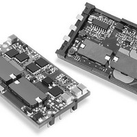
DC/DC TH 20A 48-3.3V Q-Brick
Manufacturer
Murata Power Solutions Inc
Series
ULQr
Datasheet
1.ULQ-1210-D48PM-C.pdf
(16 pages)
Specifications of ULQ-3.3/20-D48N-C
Product
Isolated
Output Power
66 W
Input Voltage Range
36 V to 75 V
Input Voltage (nominal)
48 V
Number Of Outputs
1
Output Voltage (channel 1)
3.3 V
Output Current (channel 1)
20 A
Isolation Voltage
2.25 KV
Package / Case Size
Quarter Brick
Lead Free Status / Rohs Status
Lead free / RoHS Compliant


Performance Specifi cations and Ordering Guide
* These converters are pin-for-pin/plug-compatible to competitive
** The Remote On/Off can be provided with either positive ("P" suffi x)
Pin
units. Other units may use different pin numbering or alternate
outline views. When laying out your PC board, follow the pin
FUNCTION. DOSA designates Pin 1 as +Input and Pin 3 as -Input.
or negative ("N" suffi x) polarity.
Root Model ➄
ULQ-1.5/15-D48N-C
ULQ-1.5/25-D24P-C
ULQ-1.5/25-D48N-C
ULQ-1.8/15-D48N-C
ULQ-1.8/25-D24P-C
ULQ-1.8/25-D48N-C
ULQ-2/15-D48N-C
ULQ-2/25-D24P-C
ULQ-2/25-D48N-C
ULQ-2.5/15-D48N-C
ULQ-3.3/15-D48N-C
ULQ-3.3/20-D24P-C
ULQ-3.3/20-D48N-C
ULQ-5/15-D24P-C
ULQ-5/15-D48N-C
ULQ-12/8-D24P-C
ULQ-12/10-D48N-C
1
2
3
4
➀ Typical at T
➁ Ripple/Noise (R/N) measured over a 20MHz bandwidth.
➂ Devices have no minimum-load requirements and will regulate under no-load conditions.
M E C H A N I C A L S P E C I F I C A T I O N S
ORDERING GUIDE
specifi ed with an external 1μF multi-layer ceramic and 10μF capacitors across their output pins.
Regulation specifi cations describe the output voltage deviation as the line voltage or load is
varied from its nominal/midpoint value to either extreme. (Load step = 50%.)
Remote On/Off**
DOSA-Compatible I/O Connections
Function P32
0.375 MAX.
–Output
0.600
–Input*
+Input*
(15.2)
(9.53)
A
0.125 MIN.
= +25°C under nominal line voltage and full-load conditions. All models are
(3.2)
0.300
(7.6)
(3.81)
0.150
Pin
(Volts)
5
6
7
8
V
1.5
1.5
1.5
1.8
1.8
1.8
2.5
3.3
3.3
3.3
12
12
OUT
2
2
2
5
5
Case C37, Through-Hole Package
2
1
3
Function P32
Output Trim
PLASTIC STANDOFFS
ARE RELIEVED 0.030 (0.76)
IN SOLDER JOINT AREA
(Amps)
I
+Output
+Sense
–Sense
OUT
15
25
25
15
25
25
15
25
25
15
15
20
20
15
15
10
8
➁
BOTTOM VIEW
2.00 (50.8)
2.22 (56.4)
R/N (mVp-p) ➁
Typ.
25
50
45
25
50
70
25
50
70
35
45
50
45
50
50
95
90
Dimensions are in inches (mm) shown for ref. only.
Output
Max.
Components are shown for reference only.
100
100
100
100
100
100
100
100
130
130
50
75
50
50
55
75
75
Tolerances (unless otherwise specified):
.XX ± 0.02 (0.5)
.XXX ± 0.010 (0.25)
Angles ± 2˚
➀
4
5
6
7
8
Third Angle Projection
±0.125%
±0.125%
±0.125%
±0.125%
±0.125%
±0.125%
±0.125%
±0.125%
±0.125%
±0.125%
±0.125%
±0.25%
±0.25%
±0.25%
±0.25%
±0.25%
±0.1%
@ 0.150 (3.81)
Line
www.murata-ps.com
Regulation (Max.)
0.600 (15.2)
A
4 EQ. SP.
PINS 1-3, 5-7:
PINS 4, 8:
A
0.062 ±0.001
0.040 ±0.001
(1.016 ±0.025)
(1.575 ±0.025)
Load ➂
±0.25%
±0.25%
±0.25%
±0.25%
±0.25%
±0.25%
±0.25%
±0.25%
±0.25%
±0.25%
±0.25%
±0.25%
±0.25%
±0.25%
±0.25%
±0.25%
±0.4%
➃ Nominal line voltage, no load/full load condition.
➄ Please refer to the Part Number Structure when ordering.
➅ Not all model number combinations are available. Consult Murata Power Solutions.
0.600
(15.2)
0.300
V
(7.6)
Output
Confi guration
Quarter-Brick Package
P A R T N U M B E R S T R U C T U R E
(Volts)
IN
(8.9)
0.35
48
24
48
48
24
48
48
24
48
48
48
24
48
24
48
24
48
Nom.
Nominal Output Voltage
U
Maximum Rated Output
LQ
Single Output, Low-Profi le, Quarter-Brick
1
2
3
Range
(Volts)
Surface-mount Package
Input
36-75
18-36
36-75
36-75
18-36
36-75
36-75
18-36
36-75
36-75
36-75
18-36
36-75
18-36
36-75
18-36
36-75
See page 16 for complete Part Number Structure.
-
See page 16 for the
recommneded pad
layout dimensions.
8-25 Amp Isolated DC/DC Converters
PROTECTIVE
HEAT SHIELD
3.3
Case C40
BOTTOM VIEW
2.30 (58.4)
(mA/A)
35/0.5
50/1.8
30/0.9
35/0.6
90/2.2
45/1.1
45/0.6
50/2.4
50/1.2
45/0.9
45/1.2
80/3.1
45/1.6
50/3.5
50/1.7
90/4.4
80/2.9
I
IN
/
➃
20
21 Feb 2011 MDC_ULQ-15A.B03 Page 2 of 16
-
D48
85.5%
87.5%
85.5%
85.5%
88.5%
87.5%
Min.
87%
85%
87%
86%
86%
88%
88%
89%
89%
89%
88%
4
5
6
7
8
Input Voltage Range
Effi ciency
4 EQ. SP. @ 0.150 (3.81)
ULQ Models
0.110
(2.79)
A
Remote On/Off Control Polarity
email: sales@murata-ps.com
0.125
(3.2)
N
0.600 (15.2)
OVERALL DIMENSIONS :
2.30 (58.4) x 1.45 (36.8) x 0.70 (17.8)
BEFORE REMOVAL OF PROTECTIVE
HEAT SHIELD
87.5%
87.5%
87.5%
89.5%
90.5%
89.5%
90.5%
Surface-Mount Package
(see list above)
Typ.
89%
87%
89%
89%
88%
88%
90%
91%
91%
90%
M
Lx
Pin Length Option
RoHS-6 compliant
-
C37/C40, P32
C37/C40, P32
C37/C40, P32
C37/C40, P32
C37/C40, P32
C37/C40, P32
C37/C40, P32
C37/C40, P32
C
Package
C37, P32
C37, P32
C37, P32
C37, P32
C37, P32
C37, P32
C37, P32
C37, P32
C37, P32
Pinout)
(Case,
Related parts for ULQ-3.3/20-D48N-C
Image
Part Number
Description
Manufacturer
Datasheet
Request
R

Part Number:
Description:
DC/DC TH 20A 24-3.3V Q-Brick
Manufacturer:
Murata Power Solutions Inc
Part Number:
Description:
DC/DC SM 20A 24-3.3V Q-Brick
Manufacturer:
Murata Power Solutions Inc
Datasheet:
Part Number:
Description:
DC/DC TH 20A 24-3.3V Q-Brick
Manufacturer:
Murata Power Solutions Inc
Datasheet:
Part Number:
Description:
DC/DC SM 20A 24-3.3V Q-Brick
Manufacturer:
Murata Power Solutions Inc
Datasheet:
Part Number:
Description:
DC/DC SM 20A 48-3.3V Q-Brick
Manufacturer:
Murata Power Solutions Inc
Part Number:
Description:
DC/DC TH 20A 48-3.3V Q-Brick
Manufacturer:
Murata Power Solutions Inc
Datasheet:
Part Number:
Description:
DC/DC SM 20A 48-3.3V Q-Brick
Manufacturer:
Murata Power Solutions Inc
Part Number:
Description:
DC/DC TH 15A 48-3.3V Q-Brick
Manufacturer:
Murata Power Solutions Inc
Part Number:
Description:
DC/DC SM 15A 48-3.3V Q-Brick
Manufacturer:
Murata Power Solutions Inc
Part Number:
Description:
DC/DC TH 15A 48-3.3V Q-Brick
Manufacturer:
Murata Power Solutions Inc
Part Number:
Description:
DC/DC TH 10A 48-12V Q-Brick
Manufacturer:
Murata Power Solutions Inc

Part Number:
Description:
Transformers 5Vin 5Vout 200mA 4000Vdc 1:1.33 turn
Manufacturer:
Murata Power Solutions Inc
Datasheet:

Part Number:
Description:
POWER SUPPLY
Manufacturer:
Murata Power Solutions Inc
Datasheet:

Part Number:
Description:
DPM LED MINI 2VDC 3.5DIG LP RED
Manufacturer:
Murata Power Solutions Inc
Datasheet:

Part Number:
Description:
CONV DC/DC 1W 5VIN 5VOUT SIP SGL
Manufacturer:
Murata Power Solutions Inc
Datasheet: