72-6851 TENMA, 72-6851 Datasheet - Page 16
72-6851
Manufacturer Part Number
72-6851
Description
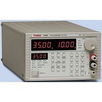
POWER SUPPLY, BENCH, 35V
Manufacturer
TENMA
Datasheet
1.72-6851.pdf
(33 pages)
Specifications of 72-6851
Power Supply Output Type
Variable
No. Of Outputs
1
Output Voltage
35V
Output Current
10A
Load Regulation
0.01%
Length
350.52mm
Width
210.82mm
Height
132.08mm
Output Type
Variable
Calibrated
No
Rohs Compliant
NA
Lead Free Status / RoHS Status
na


Tenma 72-6851 & 72-6853 Instruction manual
GPIB Subsets
GPIB IEEE Std. 488.2 Error Handling
GPIB Parallel Poll
This instrument contains the following IEEE 488.1 subsets:
*
The IEEE 488.2
If the instrument is addressed to talk and the response formatter is inactive and the input queue
is empty then the
in the Standard Event Status Register, a value of 3 to be placed in the Query Error Register and
the parser to be reset. See the Status Reporting section for further information.
The IEEE 488.2
send a response message and a
or the input queue contains more than one END message then the instrument has been
INTERRUPTED
Standard Event Status Register, a value of 1 to be placed in the Query Error Register and the
response formatter to be reset thus clearing the output queue. The parser will then start parsing
the next
further information.
The IEEE 488.2
a response message and the input queue becomes full then the instrument enters the
state and an error is generated. This will cause the Query Error bit to be set in the Standard
Event Status Register, a value of 2 to be placed in the Query Error Register and the response
formatter to be reset thus clearing the output queue. The parser will then start parsing the next
<PROGRAM MESSAGE UNIT>
information.
The power supplies offer complete parallel poll capabilities. The Parallel Poll Enable Register is
set to specify which bits in the Status Byte Register are to be used to form the
The Parallel Poll Enable Register is set by the ∗PRE <nrf> command and read by the ∗PRE?
command. The value in the Parallel Poll Enable Register is ANDed with the Status Byte Register;
if the result is zero then the value of
The instrument must also be configured so that the value of
during a parallel poll operation. The instrument is configured by the controller sending a Parallel
Poll Configure command (PPC) followed by a Parallel Poll Enable command (PPE). The bits in
the PPE command are shown below:
Although no Device Trigger capability is included, the GET message will not cause a
command error unless its position in the input stream dictates that it should; e.g. buried
inside a <PROGRAM MESSAGE UNIT>.
<PROGRAM MESSAGE UNIT>
bit 7 =
Source Handshake
Acceptor Handshake
Talker
Listener
Service Request
Remote Local
Parallel Poll
Device Clear
Device Trigger
Controller
Electrical Interface
and an error is generated. This will cause the Query Error bit to be set in the
UNTERMINATED
INTERRUPTED
DEADLOCK
UNTERMINATED
X
from the input queue. See the Status Reporting section for further
error is handled as follows. If the response formatter is waiting to send
error is handled as follows. If the response formatter is waiting to
error (addressed to talk with nothing to say) is handled as follows.
don't care
error is generated. This will cause the Query Error bit to be set
<PROGRAM MESSAGE TERMINATOR>
from the input queue. See the Status Reporting section for
www.tenma.com
ist
SH1
AH1
T6
L4
SR1
RL1
PP1
DC1
DT0*
C0
E2
is 0 otherwise the value of
ist
can be returned to the controller
ist
is 1.
has been read by the parser
ist
local message
DEADLOCK
15
Related parts for 72-6851
Image
Part Number
Description
Manufacturer
Datasheet
Request
R

Part Number:
Description:
TENMA DESOLDERING STATION, ADJUSTABLE TEMPERATURE: 410-900 DEG F, HEATER: 24 V AT 48 W, WEIGHT: 4.5 LBS, POWER: 110/120 VAC, INCLUDES: IRON HOLDER, GUN TYPE HANDLE, DIMENSIONS: (W X H X D) 8 1/4 X 6 X 6
Manufacturer:
TENMA


Part Number:
Description:
POWER SUPPLY, BENCH, 30V
Manufacturer:
TENMA
Datasheet:
Part Number:
Description:
POWER SUPPLY, BENCH, 30V
Manufacturer:
TENMA
Datasheet:
Part Number:
Description:
POWER SUPPLY, BENCH, 60V
Manufacturer:
TENMA
Datasheet:
Part Number:
Description:
POWER SUPPLY, BENCH, 18V
Manufacturer:
TENMA
Datasheet:

Part Number:
Description:
POWER SUPPLY, BENCH, 30V
Manufacturer:
TENMA
Datasheet:

Part Number:
Description:
POWER SUPPLY, BENCH, 30V/5V
Manufacturer:
TENMA
Datasheet:

Part Number:
Description:
POWER SUPPLY, BENCH, 30V/5V/12V
Manufacturer:
TENMA
Datasheet:

Part Number:
Description:
POWER SUPPLY, BENCH, 30V
Manufacturer:
TENMA
Datasheet:


Part Number:
Description:
Ribbon Cable Assembly, Header To Header, 1 Foot
Manufacturer:
Grayhill Inc
Part Number:
Description:
RS-232 To RS-422/485 Converter With 5V Operation
Manufacturer:
Grayhill Inc
Datasheet: