18D-1-20I PAYNE ENGINEERING, 18D-1-20I Datasheet - Page 2
18D-1-20I
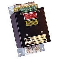
Manufacturer Part Number
18D-1-20I
Description
Variable Transformer
Manufacturer
PAYNE ENGINEERING
Datasheet
1.18D-1-10I.pdf
(4 pages)
Specifications of 18D-1-20I
Power Supply Output Type
Variable
No. Of Outputs
1
Output Voltage
118V
Power Rating
2.4kVA
Length
153mm
Width
153mm
Height
254mm
Transformer Mounting
Panel
Secondary Current Nom
20A
External Depth
3.0"
External Height
6.25"
External Width
3.5"
Rohs Compliant
NA
Lead Free Status / RoHS Status
na


Rt. 29 Scott Depot WV 25560-0070
Terminal Connections: 1 0-30 amp
use Bakelite or thermoplastic
blocks; 50 amps and larger use
screw lugs or stud bolts.
RMS Voltage Limit: circuit-board
mounted variable-resistance trim-
mer in series with manual potenti-
ometer. Allows the user to limit
output voltage to connected load at
maximum potentiometer setting.
Not applicable to units controlled by
external analog signal.
Milliamp Control: circuitry integral to
main control board that allows out-
put voltage to be controlled by exter-
nal analog signal (milliamps or d.c.
voltage) in closed-loop system. Volt-
age output from power control is
proportional to analog signal input.
Multi-turn SPAN and GAIN trimmers
provide for field calibration/adjust-
ment of signal response range.
Output Current Limit: output voltage
from control is varied to keep load
current at or below adjustable limit.
Includes current transformer.
RMS Output Voltage Regulation:
output voltage variations are limited
to
voltage may not be greater than
75% of minimum input voltage.
Isolated Chassis Construction:
electrically isolated chassis avail-
able through 80 amp size. Note: 18D
controls with “i” suffix in model num-
ber include isolated chassis con-
struction as standard feature.
Thermistor Control: control accepts
input from temperature-sensing
thermistor probe, and automatically
adjusts power control output voltage
to maintain load temperature at level
selected on temperature set potenti-
ometer in closed-loop control
scheme. Available temperature
ranges: 0-90
Thermistor probe, 3 ft. of cable, and
set-point potentiometer included.
Soft-Start:output voltage to load is
ramped from 0 to potentiometer-se-
lected level over 1/2 second after
30%. Maximum regulated output
STANDARD OPTIONS
1% for input variations up to
o
C and 90-240
o
C.
actuation to reduce inrush currents.
Operates upon closure of On/Off
switch in potentiometer and main
power activation; must be reset by
opening same switch or removing
main power before operating again.
Optically Isolated ma. Control Card:
circuit card for field retrofit of manu-
ally operated controls for automatic
control in response to external ana-
log milliamp signal. Optically iso-
lated circuit permits use in open- or
closed-loop control schemes. Volt-
age output from power control is
proportional to analog signal input.
Multi-turn SPAN and GAIN trimmers
provided for field calibration/adjust-
ment of signal response range.
Retrofit:18D (120 and 240 VAC, to
30 amps) as built prior to 8/90.
Heatsink Overtemperature Switch:
temperature sensor mounted to
heatsink switches if heatsink tem-
perature exceeds maximum allow-
able level. Available to turn off
control or drive external indicating
signal.
120 V Pilot: 120 VAC pilot voltage
used to actuate control.
70-400 Hz: control configured for
operation at frequencies ranging
from 70-400 Hz, or 16-
277 VAC Input: unit rated for sin-
gle-phase 277 VAC input.
550 VAC Input: unit rated for 550
VAC input (+10% max.).
600 VAC Input: unit rated for 600
VAC input (+10% max.).
18D/E power controls can be sup-
plied in a steel electrical enclosure
with hinged front cover. Enclosures
are ventilated to facilitate proper
cooling of the control. Ventilation
openings are covered by expanded
metal mesh, and located in the bot-
tom and the top of the side panels.
Enclosure fans are not required. For
non-ventilated enclosure require-
ments, consult local sales office.
SIZING CONSIDERATIONS
ENCLOSURES
2/3
and 25 Hz.
APPLICATION ASSISTANCE - 304/757-7354
Model 18D/E SCR power controls
are designed for use on constant-re-
sistance loads only. Size units by
actual load current, not kW.
1> Always use maximum possible
load current for sizing purposes.
2> The amp rating on all power con-
trols is determined by the fuse(s).
Current draw must not exceed the
fuse rating at any time.
3> Rated voltage of the connected
load should match the input voltage
to the power control.
Application:proportional control of
three-phase, 480 VAC, delta-con-
nected 15 kW constant-resistance
heating elements; 480 VAC,
three-phase, 60 Hz input voltage.
Model Number Selection:
a. Variable-voltage: 18
b. Three-phase: E
c. 480 VAC input: -4-
d. Amp rating, calculated as follows:
15.0 x 1000 = 18.06 amps/phase
480 x 1.73
Since 18.06<20, amp rating: 20
Model Number:18E-4-20
Options:as required.
WHEN ORDERING, SPECIFY:
Model Number
Input Voltage
Frequency
Load Specifications
Options
Enclosure Requirements
SCR Power Controls
SIZING EXAMPLE
24 HOUR FAX - 304/757-7305
Model 18D/E
Related parts for 18D-1-20I
Image
Part Number
Description
Manufacturer
Datasheet
Request
R

Part Number:
Description:
Variable Transformer
Manufacturer:
PAYNE ENGINEERING
Datasheet:
Part Number:
Description:
Variable Transformer
Manufacturer:
PAYNE ENGINEERING
Datasheet:
Part Number:
Description:
Variable Transformer
Manufacturer:
PAYNE ENGINEERING
Datasheet:
Part Number:
Description:
Variable Transformer
Manufacturer:
PAYNE ENGINEERING
Datasheet:

Part Number:
Description:
Variable Transformer, OPEN STANDARD
Manufacturer:
PAYNE ENGINEERING

Part Number:
Description:
Variable Transformer
Manufacturer:
PAYNE ENGINEERING
Datasheet:
Part Number:
Description:
Variable Transformer
Manufacturer:
PAYNE ENGINEERING
Datasheet:

Part Number:
Description:
Variable Transformer
Manufacturer:
PAYNE ENGINEERING
Datasheet:
Part Number:
Description:
Variable Transformer
Manufacturer:
PAYNE ENGINEERING
Datasheet:
Part Number:
Description:
Variable Transformer
Manufacturer:
PAYNE ENGINEERING
Datasheet:

Part Number:
Description:
Variable Transformer
Manufacturer:
PAYNE ENGINEERING
Datasheet:
Part Number:
Description:
Variable Transformer
Manufacturer:
PAYNE ENGINEERING
Datasheet:

Part Number:
Description:
Variable Transformer
Manufacturer:
PAYNE ENGINEERING
Datasheet:
Part Number:
Description:
Variable Transformer
Manufacturer:
PAYNE ENGINEERING
Datasheet: