FA1-B0-16-917-32A-BG Carling Technologies, FA1-B0-16-917-32A-BG Datasheet - Page 3
FA1-B0-16-917-32A-BG
Manufacturer Part Number
FA1-B0-16-917-32A-BG
Description
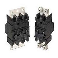
CIRCUIT BREAKER, HYD-MAG, 1P, 125V, 175A
Manufacturer
Carling Technologies
Series
Fr
Datasheet
1.FA1-B0-16-912-32A-BG.pdf
(10 pages)
Specifications of FA1-B0-16-917-32A-BG
No. Of Poles
1
Current Rating
175A
Interrupting Capacity
50kA
Dielectric Strength
1.96kV
Trip Time
150s
Voltage Rating Vdc
125V
Trip Time Max
150sec
Trip Time Min
22sec
Lead Free Status / RoHS Status
Lead free / RoHS Compliant


112
F-Series Handle – Ordering Scheme
Notes:
1
2
3
4
5
6
7
8
9
10
11
12
13
14
1
Series
F
1 SERIES
F
2 ACTUATOR
A
S
T
3 POLES
1
4 CIRCUIT
A
B
C
5 AUXILIARY/ALARM SWITCH
0
2
3
4
5
6
7
6 FREQUENCY & DELAY
03
10
11
1
2
For 100 to 250 amps, select Current Code 825. For 300-400 amps, select Current Code
840. For 450-700 amps, select Current Code 870.
Available with Frequency and Delay code 10 only, and are not rated for continuous duty.
Delay 10 is only available with voltage coils.
Codes M, N, P & Q (Parallel Poles) are supplied with factory installed Bus Bar on Line
and Load.
Metering terminals are female pin type, ref. Molex part number 02-09-1101, model 1189-
T.
Auxiliary Switch breakers are only available with Series Trip and Switch Only circuits. On
multi-pole breakers, one Auxiliary Switch is supplied, mounted in the extreme right pole
per figure A. Back-Mounted breakers require special mounting provisions when an
Auxiliary Switch is specified.
Available with parallel pole construction (circuit codes P and Q, and breakers with circuit
codes M and N).
Frequency and delay code 10 is only available with Voltage Coils. Voltage Coils are not
rated for continuous duty.
Ratings over 250 amps are only available with Agency Approval code T (UL489A) and
are Parallel Pole configuration (circuit codes M, N, P and Q.) 300-450 amp ratings are
available on two pole breakers. 500-700 amp ratings are available on three pole break-
ers.
Per UL requirement, an “Anti-Flash Over Barrier” is supplied between poles on multi-
pole breakers with 3/8 - 16 stud terminals (Terminal Code 1)
Front connected breakers can also be front mounted by utilizing the supplied front panel
mounting inserts.Terminal connections must be made before mounting.
Box Wire connector will accept #6 through 250 MCM copper wire.
Agency codes G & T must have ON-OFF or dual legends. Agency code J must have
dual legend.
Other colors available. Consult factory.
Terminals 2,4 & 5 are shipped without terminal hardware.
7
Handle, one per pole
Mid-Trip Handle, one per pole
Mid-Trip Handle, one per pole & Alarm Switch
Switch Only (No Coil)
Series Trip (Current)
Series Trip (Voltage)
w/o Aux Switch
S.P.D.T., 0.110 Q.C. Term.
S.P.D.T., 0.139 Solder Lug
S.P.D.T., 0.110 Q.C. Term.
(Gold Contacts)
S.P.S.T., 0.093 Q.C. Term.
(Gold Contacts)
S.P.S.T., 0.139 Solder Lug
S.P.S.T., 0.110 Q.C.
Term.(Gold Contacts)
DC 50/60Hz, Switch Only
DC Instantaneous
DC Ultra Short
2
Actuator
A 2
One
3
Poles
2
–
5
4
Circuit
B 0
Two
Parallel Pole Construction:
M
N
P
Q
8
9
A
B
12
14
16
3
3, 4
3
6
6
3, 4
5
Auxiliary/
Alarm Switch
Series Trip (Current) with
Metering Shunt
Switch Only with
Metering Shunt
Series Trip (Current)
Switch Only
S.P.S.T., 0.187 Q.C.
Terminals
S.P.D.T., 0.187 Q.C.
Terminals.
S.P.S.T., 0.093 Round QC
Terminals.
S.P.D.T., 0.093 Round Q.C.
Terminals.
DC Short
DC Medium
DC Long
3
–
6
Frequency
& Delay
Three
14
–
7
Current Rating
A06
A12
A18
820
7 CURRENT RATING (AMPERES)
810
912
815
917
OR VOLTAGE COIL (VOLTS, MIN. TRIP RATING)
8 TERMINAL
Back Connected (Front Mounted Only)
1
2
5
Front Connected (Back Mounted Only)
3
4
9 ACTUATOR COLOR & LEGEND
Actuator:
White
Black
11 MAXIMUM APPLICATION RATING
B
12 AGENCY APPROVAL
A
G
J
T
10 MOUNTING
A
B
9
14
14
14
Voltage
125 VDC
12 DC, 10 DC
18 DC, 15 DC
3/8-16 Stud
3/8-16 Screw, Line & Load
3/8-16 Short Stud
Box Wire Connector, Line & Load
3/8-16 Screw, Line & Load
UL 489 Listed & CUL Certified
UL 489 Listed, CUL Certified & TUV Certified
UL489A (Telecom) Listed
100.00
125.00
150.00
175.00
Front Mounting Inserts
10-32
ISO M5
No approvals
6 DC, 5 DC
Marking:
A
C
I-O
–
820
922
825
830
ON-OFF
B
D
8
Terminal
1 2
8
Current
700A
200.00
225.00
250.00
300.00
A24
A32
A48
9
Actuator
Color
Dual
1
2
24 DC, 20 DC
32 DC, 25 DC
48 DC, 40 DC
12,13
Back Mounting Inserts
10-32 screw clearance holes
10-32 screw clearance holes
11
835
840
845
850
Marking Color:
Black
White
10
Mounting
8
8
8
8
www.carlingtech.com
A
350.00
400.00
450.00
500.00
7
–
A65
B25 125 DC, 100 DC
J06
11
Max. App.
Rating
Max Rating
250A
700A
250A
Max Rating
700A
700A
B G
860
870
65 DC, 55 DC
6 AC, 5 AC
8
8
600.00
700.00
12
Agency
Approval
Related parts for FA1-B0-16-917-32A-BG
Image
Part Number
Description
Manufacturer
Datasheet
Request
R

Part Number:
Description:
CIRCUIT BREAKER 125A 125DC F-SER
Manufacturer:
Carling Technologies
Datasheet:
Part Number:
Description:
Toggle Switches CARLING TECHNOLOGIES
Manufacturer:
Carling Technologies
Datasheet:
Part Number:
Description:
CARLING POWER SWITCH LIGHTED 10 AMP 250 VOLT AC
Manufacturer:
Carling Technologies
Part Number:
Description:
CARLING SWITCH
Manufacturer:
Carling Technologies

Part Number:
Description:
SWITCH PB SPST OFF-MOM SCRW TERM
Manufacturer:
Carling Technologies
Datasheet:
Part Number:
Description:
LIGHT INDICATOR GRN 12VDC PNLMNT
Manufacturer:
Carling Technologies
Part Number:
Description:
CONTURA ILL INDICATOR 12V RED
Manufacturer:
Carling Technologies
Part Number:
Description:
Current Regulator Diodes CURRENT REGULATOR DIODES 3.6mA
Manufacturer:
Carling Technologies
Part Number:
Description:
Rocker Switches
Manufacturer:
Carling Technologies
Datasheet: