VS-GT100LA120UX Vishay, VS-GT100LA120UX Datasheet - Page 7
VS-GT100LA120UX
Manufacturer Part Number
VS-GT100LA120UX
Description
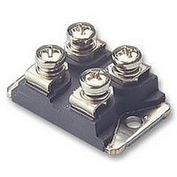
TRANSISTOR,IGBT,1200V,100A,SOT227
Manufacturer
Vishay
Datasheet
1.VS-GT100LA120UX.pdf
(9 pages)
Specifications of VS-GT100LA120UX
Transistor Type
IGBT
Dc Collector Current
134A
Collector Emitter Voltage Vces
2.36V
Power Dissipation Max
463W
Collector Emitter Voltage V(br)ceo
1.2kV
Operating Temperature Range
-40°C To
Lead Free Status / RoHS Status
Lead free / RoHS Compliant


Document Number: 93099
Revision: 22-Jul-10
50 V
* Driver same type as D.U.T.; V
* Note: Due to the 50 V power supply, pulse width and inductor
Fig. 18a - Clamped Inductive Load Test Circuit
will increase to obtain Id
1
1000 V
DiodesAmericas@vishay.com, DiodesAsia@vishay.com,
For technical questions within your region, please contact one of the following:
1
2
3
V
I
C
C
C
= 80 % of V
5 %
L
V
10 %
90 %
C
"Low Side Chopper" IGBT SOT-227
*
Fig. 19b - Switching Loss Waveforms Test Circuit
ce(max)
Diode clamp/
Fig. 19a - Switching Loss Test Circuit
D.U.T.
t
D.U.T.
d(on)
(Trench IGBT), 100 A
- 5 V
-
2
+
R
g
10 %
t
r
E
on
E
D.U.T./
L
driver
ts
= (E
on
+ E
t
d(off)
90 %
off
Fig. 18b - Pulsed Collector Current Test Circuit
DiodesEurope@vishay.com
)
+
-
V
CC
E
t
f
off
R
g
Vishay Semiconductors
t = 5 µs
D.U.T.
GT100LA120UX
R =
V
I
CM
CC
www.vishay.com
+
-
V
CC
7
Related parts for VS-GT100LA120UX
Image
Part Number
Description
Manufacturer
Datasheet
Request
R

Part Number:
Description:
357-036-542-201 CARDEDGE 36POS DL .156 BLK LOPRO
Manufacturer:
Vishay
Datasheet:
Part Number:
Description:
357-036-542-201 CARDEDGE 36POS DL .156 BLK LOPRO
Manufacturer:
Vishay
Datasheet:
Part Number:
Description:
357-036-542-201 CARDEDGE 36POS DL .156 BLK LOPRO
Manufacturer:
Vishay
Datasheet:
Part Number:
Description:
357-036-542-201 CARDEDGE 36POS DL .156 BLK LOPRO
Manufacturer:
Vishay
Datasheet:
Part Number:
Description:
357-036-542-201 CARDEDGE 36POS DL .156 BLK LOPRO
Manufacturer:
Vishay
Datasheet:
Part Number:
Description:
357-036-542-201 CARDEDGE 36POS DL .156 BLK LOPRO
Manufacturer:
Vishay
Datasheet:
Part Number:
Description:
357-036-542-201 CARDEDGE 36POS DL .156 BLK LOPRO
Manufacturer:
Vishay
Datasheet:
Part Number:
Description:
357-036-542-201 CARDEDGE 36POS DL .156 BLK LOPRO
Manufacturer:
Vishay
Datasheet:
Part Number:
Description:
357-036-542-201 CARDEDGE 36POS DL .156 BLK LOPRO
Manufacturer:
Vishay
Datasheet:
Part Number:
Description:
357-036-542-201 CARDEDGE 36POS DL .156 BLK LOPRO
Manufacturer:
Vishay
Datasheet:
Part Number:
Description:
357-036-542-201 CARDEDGE 36POS DL .156 BLK LOPRO
Manufacturer:
Vishay
Datasheet:
Part Number:
Description:
357-036-542-201 CARDEDGE 36POS DL .156 BLK LOPRO
Manufacturer:
Vishay
Datasheet:
Part Number:
Description:
357-036-542-201 CARDEDGE 36POS DL .156 BLK LOPRO
Manufacturer:
Vishay
Datasheet:
Part Number:
Description:
357-036-542-201 CARDEDGE 36POS DL .156 BLK LOPRO
Manufacturer:
Vishay
Datasheet:
Part Number:
Description:
357-036-542-201 CARDEDGE 36POS DL .156 BLK LOPRO
Manufacturer:
Vishay
Datasheet: