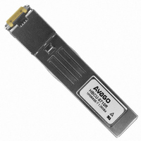
HBCU-5710R Avago Technologies US Inc., HBCU-5710R Datasheet - Page 2

HBCU-5710R
Manufacturer Part Number
HBCU-5710R
Description
Fiber Optic Transceiver,Module
Manufacturer
Avago Technologies US Inc.
Datasheet
1.HBCU-5710R.pdf
(25 pages)
Specifications of HBCU-5710R
Data Rate
1.25Gbps
Wavelength
850nm
Voltage - Supply
3.3V
Connector Type
RJ45
Mounting Type
Through Hole
Lead Free Status / RoHS Status
Lead free / RoHS Compliant
Applications
-
Lead Free Status / RoHS Status
Lead free / RoHS Compliant, Contains lead / RoHS non-compliant
Other names
516-2009
Available stocks
Company
Part Number
Manufacturer
Quantity
Price
Module Diagrams
Figure 1 illustrates the major functional components
of the HBCU-5710R. The 20-pin connection diagram of
module printed circuit board of the module is shown in
Figure 2. Figure 3 depicts the pin assignment of the MDI
(RJ45 jack).
Figure 7 depicts the external configuration and dimen-
sions of the module.
Installation
The HBCU-5710R can be installed in or removed from
any MultiSource Agreement (MSA) compliant Small Form
Pluggable port whether the host equipment is operating
or not. The module is simply inserted, small end first, un-
der finger-pressure. Controlled hot-plugging is ensured
by design and by 3-stage pin sequencing at the electrical
interface to the host board. The module housing makes
initial contact with the host board EMI shield, mitigating
potential damage due to Electro-Static Discharge (ESD).
The module pins sequentially contact the (1) Ground,
(2) Power, and (3) Signal pins of the host board surface
mount connector. This printed circuit board card-edge
connector is depicted in Figure 2.
Serial Identification (EEPROM)
The HBCU-5710R complies with an industry standard
MultiSource Agreement that defines the serial identifica-
tion protocol. This protocol uses the 2-wire serial CMOS
EEPROM protocol of the ATMEL AT24C01A or equivalent.
The contents of the HBCU-5710R serial ID memory are
defined in Table 3 as specified in the SFP MSA.
RATE_SELECT
Figure 1: Transceiver Functional Diagram
2
TX_DISABLE
MOD_DEF2
MOD_DEF1
MOD_DEF0
TX_FAULT
TX_DATA
RX_DATA
RX_LOS
NC
EEPROM
SerDes/
DSP
A
D
C
B
Magnetics
Controller and Data I/O
Data I/Os are designed to accept industry standard dif-
ferential signals. In order to reduce the number of passive
components required on the customer’s board, Avago
Technologies has included the functionality of the trans-
mitter bias resistors and coupling capacitors within the
module. The transceiver is compatible with an “ac-cou-
pled” configuration and is internally terminated. Figure
1 depicts the functional diagram of the HBCU-5710R.
Caution should be taken into account for the proper
interconnection between the supporting Physical Layer
integrated circuits and the HBCU-5710R. Figure 4 illus-
trates the recommended interface circuit.
Several control data signals and timing diagrams are imple-
mented in the module and are depicted in Figure 6.
Note: TX_FAULT and Rate_Select not used.
Figure 2: 20-pin Connection Diagram of Module Printed Circuit Board
RJ45
Adapter
20
19
18
17
16
15
14
13
12
11
Top of Board
V
TD-
TD+
V
V
V
V
RD+
RD-
V
EE
EE
CC
CC
EE
EE
T
T
R
R
T
R
10
(as viewed thru top of board)
1
2
3
4
5
6
7
8
9
Bottom of Board
V
TX_FAULT
TX_DISABLE
MOD-DEF(2)
MOD-DEF(1)
MOD-DEF(0)
Rate Select
LOS
V
V
EE
EE
EE
T
R
R


