SLW360 TIMEGUARD, SLW360 Datasheet - Page 6
SLW360
Manufacturer Part Number
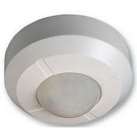
SLW360
Description
PIR, 360 DEG, SURFACE MOUNT, CEILING
Manufacturer
TIMEGUARD
Datasheet
1.SLW360.pdf
(12 pages)
Specifications of SLW360
Beam Angle
360°
Length
53mm
Depth
103mm
Colour
White
External Width
103mm
Contact Voltage Ac Max
230V
Frequency
50Hz
Mounting Type
Surface Mount
Range
6m
Svhc
No SVHC (15-Dec-2010)
Rohs Compliant
NA
Lead Free Status / RoHS Status
na


5
PIERCE & PASS THE INCOMING AND OUTGOING
CABLE THROUGH THE GROMMET BEFORE
SECURING CEILING MOUNTING PLATE TO
CEILING.
It is recommended that the grommet is pierced with a
screwdriver to ensure a better seal.
Connection
THERE ARE 2 POSSIBLE CONNECTION SCENARIOS
1. Standard connection. See Diagram G.
The factory fitted “bridge” wire must not be removed.
Connect the 4 core mains supply cable to the terminal
block on the unit as follows:-
NEUTRAL (Blue)
EARTH (Green/Yellow)
LIVE (Brown)
Connect the fourth core cable or incoming cable from
the lighting load to the L1 terminal block on the unit as
follows (see connection diagram G)
SWITCHED LIVE L1
2. Switching DC loads or loads which use a different
phase or voltage supply from the AC mains. See
Diagram H. Remove the factory fitted bridge wire.
Connect the 3 core mains supply cable to the terminal
block on the unit as follows:-
NEUTRAL (Blue)
EARTH (Green/Yellow)
LIVE (Brown)
Connect the load in series with the load supply
between L1 and L2 terminals.
Please note that the function of L1 and L2 can viewed
as a simple switch controlled by the PIR sensor
electronics.
When wiring is complete, it is recommended that the
ceiling mounting plate is fitted to the sensor
body and fixed to the ceiling as follows:-
N
L
N
L
Related parts for SLW360
Image
Part Number
Description
Manufacturer
Datasheet
Request
R


Part Number:
Description:
Amber Strobe, Power Requirements: 12 VDC, 180 MA, Features: For 3-14 VDC Applications, U Type Xenon Tube Over 100000 Candle Power, Water Tight O Ring For Indoor Use
Manufacturer:
SECO-LARM

Part Number:
Description:
LAMP, BULKHEAD, PIR, BC, TIMEGUARD
Manufacturer:
TIMEGUARD
Datasheet:

Part Number:
Description:
LAMP, BULKHEAD, PIR, BC, TIMEGUARD
Manufacturer:
TIMEGUARD
Datasheet:

Part Number:
Description:
OUTLET, RCD FUSED, 13A, LATCHING
Manufacturer:
TIMEGUARD
Datasheet:

Part Number:
Description:
SPARE LAMPS FOR NIGHT LIGHT
Manufacturer:
TIMEGUARD
Datasheet:
Part Number:
Description:
BULKHEAD LIGHT, PYRAMID, 18W
Manufacturer:
TIMEGUARD
Datasheet:
Part Number:
Description:
WALL LIGHT, 360 DEG PIR, 22W
Manufacturer:
TIMEGUARD
Datasheet:
Part Number:
Description:
PRESENCE DETECTOR, PIR, FLUSH, 2000W
Manufacturer:
TIMEGUARD
Datasheet:
Part Number:
Description:
PRESENCE, PIR, FLUSH, 2000W, 2CH
Manufacturer:
TIMEGUARD
Datasheet:
Part Number:
Description:
PRSNCE DTCTR, PIR, SM, 2000W, 2 CH
Manufacturer:
TIMEGUARD
Datasheet:

Part Number:
Description:
FLOODLIGHT, PIR, 150W
Manufacturer:
TIMEGUARD
Datasheet:

Part Number:
Description:
FLOODLIGHT, PIR, 500W
Manufacturer:
TIMEGUARD
Datasheet:

Part Number:
Description:
PIR CONTROLLER, 360 DEG, FM, WHITE
Manufacturer:
TIMEGUARD
Datasheet:

Part Number:
Description:
CONN RCPT .100" 12POS SGL 30GOLD
Manufacturer:
Samtec Inc
Datasheet: