PT100MC0MP Sharp Microelectronics, PT100MC0MP Datasheet - Page 6
PT100MC0MP
Manufacturer Part Number
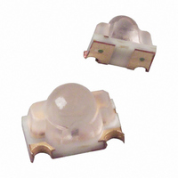
PT100MC0MP
Description
TRANSISTOR, PHOTO, 900NM, SMD
Manufacturer
Sharp Microelectronics
Type
Phototransistorr
Specifications of PT100MC0MP
Transistor Polarity
NPN
Wavelength Typ
900nm
Power Consumption
75mW
Viewing Angle
15°
No. Of Pins
2
Collector Emitter Saturation Voltage Vce(sat)
0.4V
Rise Time
5µs
Peak Wavelength
900nm
Maximum Power Dissipation
75 mW
Maximum Dark Current
100 nA
Collector- Emitter Voltage Vceo Max
35 V
Fall Time
6 us
Maximum Operating Temperature
+ 85 C
Minimum Operating Temperature
- 30 C
Package / Case
SMD
Voltage - Collector Emitter Breakdown (max)
35V
Current - Collector (ic) (max)
20mA
Current - Dark (id) (max)
100nA
Wavelength
900nm
Power - Max
75mW
Mounting Type
Surface Mount
Orientation
Universal
Rohs Compliant
Yes
Half Sensitivity Angle ±
15°
Lead Free Status / RoHS Status
Lead free / RoHS Compliant
Lead Free Status / RoHS Status
Lead free / RoHS Compliant, Lead free / RoHS Compliant
Available stocks
Company
Part Number
Manufacturer
Quantity
Price
Company:

Part Number:
PT100MC0MP
Manufacturer:
SHARP
Quantity:
5 143
Company:
Part Number:
PT100MC0MP1
Manufacturer:
LITEON
Quantity:
17 776


■ Design Considerations
1. This product is not designed to be electromagnetic- and ionized-particle-radiation resistant.
■ Manufacturing Guidelines
1. Sharp recommends soldering no more than once when using solder reflow methods.
2. When using solder reflow methods, follow the reflow soldering temperature profile shown in Fig. 10. Sharp rec-
3. If using an infrared lamp to preheat the parts, such heat sources may cause localized high temperatures in the
4. If hand soldering, use temperatures ≤ 240° for ≤ 3 seconds. Do not dip-solder or VPS-solder this part.
5. Do not subject the package to excessive mechanical force during soldering as it may cause deformation or
Fig. 10 Reflow Soldering Temperature Profile
240°C MAX.
165°C MAX.
1. Confirm this device's resistance to process chemicals before use, as certain process chemicals may affect the
2. Solvent cleaning: Solvent temperature should be 45°C or below. Immersion time should be 3 minutes or less.
3. Ultrasonic cleaning: The effect upon devices varies due to cleaning bath size, ultrasonic power output, cleaning
4. Recommended solvent materials: Ethyl alcohol, Methyl alcohol, and Isopropyl alcohol.
Design Guidelines
Soldering Instructions
Cleaning Instructions
ommends checking the process to make sure these parameters are not exceeded; exceeding these parameters
can cause substrate bending or other mechanical stresses leading to debonding of the internal gold wires, or
other similar failure modes.
part's resin. Be sure to keep the temperature profile within the guidelines shown in Fig. 10.
defects in plated connections. Internal connections may be severed due to mechanical force placed on the pack-
age due to the PCB flexing during the soldering process.
optical characteristics.
time, PCB size and device mounting circumstances. Sharp recommends testing using actual production condi-
tions to confirm the harmlessness of the ultrasonic cleaning methods.
200°C
25°C
1 to 4°C/s
120s MAX.
1 to 4°C/s
90s MAX.
10s MAX.
60s MAX.
1 to 4°C/s
6
PT100MC0MPx
Sheet No.: D1-A01701EN
Related parts for PT100MC0MP
Image
Part Number
Description
Manufacturer
Datasheet
Request
R

Part Number:
Description:
TRANSFORMER, PULSE, 2:1
Manufacturer:
OEP (OXFORD ELECTRICAL PRODUCTS)
Datasheet:

Part Number:
Description:
Power Inductors 10uH 15% .02ohm HznMnt Toroid PwrInd
Manufacturer:
API Delevan Inc
Part Number:
Description:
Power Inductors 10uH 15% .02ohm VrtMnt Toroid Radial
Manufacturer:
API Delevan Inc
Datasheet:
Part Number:
Description:
Power Inductors 10uH 15% .01ohm VrtMnt Toroid Radial
Manufacturer:
API Delevan Inc
Part Number:
Description:
Power Inductors 10uH 15% .01ohm HznMnt Toroid PwrInd
Manufacturer:
API Delevan Inc
Part Number:
Description:
Power Inductors 10uH 15% .008ohm VrtMnt Toroid Radial
Manufacturer:
API Delevan Inc
Part Number:
Description:
Power Inductors 10uH 15% .008ohm HznMnt Toroid PwrInd
Manufacturer:
API Delevan Inc
Part Number:
Description:
Power Inductors 10uH 15% .02ohm VrtMnt 2LeadClip Tor
Manufacturer:
API Delevan Inc
Datasheet:
Part Number:
Description:
Power Inductors 10uH 15% .015ohm VrtMnt Toroid Radial
Manufacturer:
API Delevan Inc
Datasheet:
Part Number:
Description:
Power Inductors 10uH 15% .015ohm HznMnt Toroid PwrInd
Manufacturer:
API Delevan Inc

Part Number:
Description:
IC FLASH 32MBIT 110NS 56SSOP
Manufacturer:
Sharp Microelectronics
Datasheet:

Part Number:
Description:
IC FLASH 16MBIT 100NS 56TSOP
Manufacturer:
Sharp Microelectronics
Datasheet:

Part Number:
Description:
IC FLASH 64MBIT 120NS 56TSOP
Manufacturer:
Sharp Microelectronics
Datasheet:

Part Number:
Description:
IC FLASH 16MBIT 90NS 48TSOP
Manufacturer:
Sharp Microelectronics
Datasheet:
Part Number:
Description:
IC SRAM 16KBIT 100NS 24DIP
Manufacturer:
Sharp Microelectronics
Datasheet: