ADXL203EB Analog Devices Inc, ADXL203EB Datasheet - Page 11
ADXL203EB
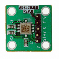
Manufacturer Part Number
ADXL203EB
Description
±1.7g Dual-Axis IMEMS Accelerometer Evaluation Board
Manufacturer
Analog Devices Inc
Series
iMEMS®r
Specifications of ADXL203EB
Silicon Manufacturer
Analog Devices
Application Sub Type
Accelerometer - Dual-Axis
Kit Application Type
Sensing - Motion / Vibration / Shock
Silicon Core Number
ADXL203
Sensor Type
Accelerometer, 2 Axis
Sensing Range
±1.7g
Interface
Analog
Sensitivity
1000mV/g
Voltage - Supply
3 V ~ 6 V
Embedded
No
Utilized Ic / Part
ADXL203
Lead Free Status / RoHS Status
Contains lead / RoHS non-compliant
Other names
Q1875695


Peak-to-peak noise values give the best estimate of the uncertainty
in a single measurement; peak-to-peak noise is estimated by
6 × rms. Table 8 gives the typical noise output of the ADXL103/
ADXL203 for various C
Table 8. Filter Capacitor Selection (C
Bandwidth (Hz)
10
50
100
500
USING THE ADXL103/ADXL203 WITH OPERATING
VOLTAGES OTHER THAN 5 V
The ADXL103/ADXL203 is tested and specified at V
however, it can be powered with V
6 V. Some performance parameters change as the supply voltage
is varied.
The ADXL103/ADXL203 output is ratiometric, so the output
sensitivity (or scale factor) varies proportionally to supply
voltage. At V
The zero g bias output is also ratiometric, so the zero g output is
nominally equal to V
The output noise is not ratiometric but is absolute in volts;
therefore, the noise density decreases as the supply voltage
increases. This is because the scale factor (mV/g) increases
while the noise voltage remains constant. At V
density is typically 190 μg/√Hz.
Self-test response in g is roughly proportional to the square of
the supply voltage. However, when ratiometricity of sensitivity
is factored in with supply voltage, self-test response in volts is
roughly proportional to the cube of the supply voltage. So at
V
150 mV or equivalent to 270 mg (typical).
The supply current decreases as the supply voltage decreases.
Typical current consumption at V
S
= 3 V, the self-test response is approximately equivalent to
S
= 3 V the output sensitivity is typically 560 mV/g.
C
(μF)
0.47
0.1
0.047
0.01
X
S
/2 at all supply voltages.
, C
X
Y
and C
RMS Noise
(mg)
0.4
1.0
1.4
3.1
Y
values.
DD
S
as low as 3 V or as high as
= 3 V is 450 μA.
X
, C
Y
Peak-to-Peak Noise
Estimate (mg)
2.6
6
8.4
18.7
)
S
= 3 V, the noise
S
= 5 V;
Rev. C | Page 11 of 12
USING THE ADXL203 AS A DUAL-AXIS TILT
SENSOR
One of the most popular applications of the ADXL203 is tilt
measurement. An accelerometer uses the force of gravity as an
input vector to determine the orientation of an object in space.
An accelerometer is most sensitive to tilt when its sensitive axis
is perpendicular to the force of gravity, that is, parallel to the
earth’s surface. At this orientation, its sensitivity to changes in
tilt is highest. When the accelerometer is oriented on axis to
gravity, that is, near its +1 g or –1 g reading, the change in
output acceleration per degree of tilt is negligible. When the
accelerometer is perpendicular to gravity, its output changes
nearly 17.5 mg per degree of tilt. At 45°, its output changes at
only 12.2 mg per degree, and resolution declines.
Dual-Axis Tilt Sensor: Converting Acceleration to Tilt
When the accelerometer is oriented so both its x axis and y axis
are parallel to the earth’s surface, it can be used as a 2-axis tilt
sensor with a roll axis and a pitch axis. Once the output signal
from the accelerometer has been converted to an acceleration
that varies between –1 g and +1 g, the output tilt in degrees is
calculated as follows:
Be sure to account for overranges. It is possible for the
accelerometers to output a signal greater than ±1 g due to
vibration, shock, or other accelerations.
PITCH = ASIN(A
ROLL = ASIN(A
Y
/1 g)
X
/1 g)
ADXL103/ADXL203
Related parts for ADXL203EB
Image
Part Number
Description
Manufacturer
Datasheet
Request
R

Part Number:
Description:
Analog MCU Evaluation Board
Manufacturer:
Analog Devices Inc
Datasheet:
Part Number:
Description:
Inertial Sensor Evaluation System
Manufacturer:
Analog Devices Inc
Datasheet:
Part Number:
Description:
Manufacturer:
Analog Devices Inc
Datasheet:
Part Number:
Description:
Manufacturer:
Analog Devices Inc
Datasheet:
Part Number:
Description:
Manufacturer:
Analog Devices Inc
Datasheet:
Part Number:
Description:
Manufacturer:
Analog Devices Inc
Datasheet:
Part Number:
Description:
Manufacturer:
Analog Devices Inc
Datasheet:
Part Number:
Description:
Manufacturer:
Analog Devices Inc
Datasheet:
Part Number:
Description:
Manufacturer:
Analog Devices Inc
Datasheet:
Part Number:
Description:
Manufacturer:
Analog Devices Inc
Datasheet:
Part Number:
Description:
Manufacturer:
Analog Devices Inc
Datasheet:
Part Number:
Description:
Manufacturer:
Analog Devices Inc
Datasheet:
Part Number:
Description:
Manufacturer:
Analog Devices Inc
Datasheet: