FLEX104 EVIDENCE, FLEX104 Datasheet - Page 7
FLEX104
Manufacturer Part Number
FLEX104
Description
Development Tools & Eval/Demo Boards
Manufacturer
EVIDENCE
Datasheet
1.FLEX103.pdf
(41 pages)
Specifications of FLEX104
Silicon Manufacturer
Microchip
Application Sub Type
FLEX Multibus RS485 Module
Kit Application Type
Communication & Networking
Kit Contents
Board
Supply Voltage Range
7V To 12V, 9V To 36V
Lead Free Status / RoHS Status
Lead free / RoHS Compliant


3 Architecture
The modular architecture provided by FLEX allows to compound a number of boards to
integrate different features into a single device.
Base Board mounts a Microchip dsPIC (R) DSC micro-controller, and exports almost all
the pins of the micro-controller. The user can easily connect the desired components to
the dsPIC (R) DSC ports in order to build the specific application.
to the FLEX Base Board. The daughter boards have different features and they can
be easily combined to obtain complex devices. Evidence S.r.l. and Embedded Solutions
S.r.l. supplies a growing number of daughter boards for basic and advanced applications.
3.1 Base board
The FLEX Base Board is designed to export all the connections of a standard Microchip
dsPIC (R) DSC micro-controller. The board connections use the standard 2.54 mm pitch:
this feature make it easy the usage of custom, home-made daughter boards.
dsPIC (R) DSC controller welded on the board surface, and a socket for installing the
micro-controller through the interchangeable Plug-In Modules (PIMs) available from Mi-
crochip. The availability of the latter option allows the developer to forget any limit on
the number of programming cycles during the implementation/test/debugging phases:
a new PIM can be installed on the socket in case of any problem to the older one.
application developed with the Full Version can be easily moved to the Light Version
and vice-versa, i.e., without any modification to the control program.
3.1.1 Base board: Full version
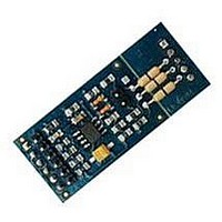
The Full FLEX Base Board, depicted in Figure 3.3, integrates an extra-robust power
supply circuitry, which allows the usage of a wide range of power suppliers.
adapted to the internal levels. Figure
The basic configuration of a FLEX device is made by the Base Board only. The FLEX
As depicted in Figure 3.1, several daughter boards can be connected in piggyback
The board have two options for using onboard dsPIC (R) DSC micro-controllers:
The FLEX Base Board is available in two versions:
The connectors are fully compatible between Full and Light Versions, so that an
It accepts voltage ranges between 9 - 36 V. The power supply signal is filtered and
• Full version, showed in Section 3.1.1;
• Light version, showed in Section 3.1.2.
3.4
shows a rear view of the Flex Full board. on
7
Related parts for FLEX104
Image
Part Number
Description
Manufacturer
Datasheet
Request
R

Part Number:
Description:
FLEX Light Base Board
Manufacturer:
EVIDENCE
Datasheet:

Part Number:
Description:
FLEX MultiBus Daughter Board
Manufacturer:
EVIDENCE
Datasheet:

Part Number:
Description:
FLEX Demo Daughter Board
Manufacturer:
EVIDENCE
Datasheet:

Part Number:
Description:
FLEX Full Base Board
Manufacturer:
EVIDENCE
Datasheet:

Part Number:
Description:
FLEX Blank Thru-Hole Daughter Board
Manufacturer:
EVIDENCE
Datasheet:

Part Number:
Description:
FLEX Multibus Ethernet Module
Manufacturer:
EVIDENCE
Datasheet:

Part Number:
Description:
FLEX Multibus RS232 Module
Manufacturer:
EVIDENCE
Datasheet:

Part Number:
Description:
FLEX Multibus RS422 Module
Manufacturer:
EVIDENCE
Datasheet:

Part Number:
Description:
FLEX Multibus CAN Module
Manufacturer:
EVIDENCE
Datasheet:

Part Number:
Description:
FLEX Multibus SPI Module
Manufacturer:
EVIDENCE
Datasheet:


Part Number:
Description:
Microcontroller & Microprocessor Development Tools Demo2 Pack
Manufacturer:
EVIDENCE
Datasheet:

Part Number:
Description:
Microcontroller & Microprocessor Development Tools Mini Kit
Manufacturer:
EVIDENCE
Datasheet:

Part Number:
Description:
Microcontroller & Microprocessor Development Tools Multibus Pack
Manufacturer:
EVIDENCE
Datasheet: