IPR-10GETHERNET Altera, IPR-10GETHERNET Datasheet
IPR-10GETHERNET
Specifications of IPR-10GETHERNET


Related parts for IPR-10GETHERNET


IPR-10GETHERNET Summary of contents
Page 1
... Innovation Drive San Jose, CA 95134 www.altera.com 10-Gbps Ethernet Reference Design User Guide IP Core Version: 10.0 Document Date: July 2010 ...
Page 2
... July 2010 Altera Corporation UG-01076-2.0 i–2 10-Gbps Ethernet Reference Design User Guide ...
Page 3
... Note to Figure 1–1: (1) You can implement the optional XAUI PCS in an Altera device transceiver or as soft logic, which results in a soft 10GBASE-X XAUI PCS and PMA. 1.1. Supported Features Flexible standard interfaces: SDR XGMII-like interface to connect to the internal ■ 10GBASE-X (XAUI) PHY, standard XGMII interface to connect to the external PHY device, hard IP XAUI PCS and PMA to connect to an external optical module. ■ ...
Page 4
... Programmable filtering of received frames with CRC errors, length-check error, or oversized errors. ■ Easy-to-use MegaWizard ■ IP functional simulation models for use in Altera-supported VHDL and Verilog HDL simulators. Verilog HDL and VHDL testbench and verification environment. ■ ■ Deficit Idle Count (DIC) is supported 1.2. Performance and Resource Utilization Table 1– ...
Page 5
... On the XGMII interface, the Tx now transmits with a clock ■ ° shifted 90 and the Rx interface expects a clock that is shifted by 90 Corrected address for linkFaultDetect register. ■ © July 2010 Altera Corporation Combinational Logic ECC ALUTs Registers Yes No 5,666 ...
Page 6
... Full support means the IP core meets all functional and timing requirements for the device family and can be used in production designs. 10-Gbps Ethernet IP Datasheet New Features Revision History Device Support Device Support Added Level Arria II GX Preliminary Arria GX Full (2) Stratix II Full Stratix II GX Full Stratix III Full Stratix IV Preliminary © July 2010 Altera Corporation ...
Page 7
... Quartus f Refer to the Quartus II Development Software Literature the Quartus II design flow, including tutorials. 1 Altera categorizes this IP core as a reference design, described on the Altera website on the 10-Gbps Ethernet Reference Design This document describes the following development flow steps: 1. Licensing and Installation a ...
Page 8
... For more information about the OpenCore Plus hardware evaluation, refer to AN 320: OpenCore Plus Evaluation of 2.1.2. Purchasing Full License for System Development The use of this 10-Gbps Ethernet IP core is governed by, and is subject to, the terms and conditions of the Altera License Terms and Conditions for 10-Gbps Ethernet IP core. f Refer to License Terms and Conditions for 10-Gbps Reference Design purchasing a full production license ...
Page 9
... Install IP Core Library for MegaWizard Plug-In Manager Flow Complete the following steps to install the design files for the MegaWizard Plug-In Manager design flow: 1. Choose Programs > Altera > Quartus II><version number> (Windows Start menu) to run the Quartus II software create a Quartus II project, complete the following steps: a ...
Page 10
... Click OK the File menu click Save Project. Type the project name tgb_91. You are now ready to create variations of the Altera 10-Gbps Ethernet design using the MegaWizard Plug-In Manager. You can locate the 10-Gbps Ethernet IP core in the MegaWizard Plug-In Manager by expanding Installed Plug-Ins > Interfaces > ...
Page 11
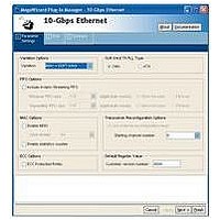
... Parameter Settings MAC + XGMII MAC + XAUI MAC + Soft XAUI © July 2010 Altera Corporation Description Creates a IP core with a media access control (MAC) using an Avalon (Avalon-ST) interface on the client side and 32-bit standard DDR XGMII interface operating at 156.25 MHz on the network side. ...
Page 12
... When you select Store forward, you should select the FIFO size to accommodate the longest possible frame in the system with some overhead. Altera recommends twice the maximum possible frame size as a minimum. In most cases, Store forward mode increases the latency and requires a deeper FIFO ...
Page 13
... In any configuration that requires the ALTGX_RECONFIG megafunction, you must instantiate it in your design and connect it to the 10-Gbps Ethernet IP core as shown in Figure 2–3. © July 2010 Altera Corporation Description When you turn this option On, the IP core instantiates an management data I/O (MDIO) master. The MDIO interface provides an Avalon Memory-Mapped (Avalon-MM) to MDIO bridge to control an external PHY ...
Page 14
... Getting Started with the 10-Gbps Ethernet IP Chapter 2: Getting Started with the 10-Gbps Ethernet IP reconfig_fromgxb[<n-1>:0] reconfig_togxb[<n-1>:0] Design Flows ALTGX or ALT2GX Megafunction reconfig_fromgxb[<n-1>:0] reconfig_togxb[<n-1>:0] reconfig_clk cal_blk_clk 10G Ethernet IP Core Guide. Error Correction Code Guide. © July 2010 Altera Corporation ...
Page 15
... DMA controllers, you can quickly create an SOPC Builder system with an Ethernet interface. 2.3.2.1. Specify Parameters Follow the steps below to specify 10-Gbps Ethernet parameters using the SOPC Builder flow. © July 2010 Altera Corporation 2–9 “IP Core Parameterization” Getting Started with the 10-Gbps Ethernet IP ...
Page 16
... Max Channel Include Packet Support Getting Started with the 10-Gbps Ethernet IP Chapter 2: Getting Started with the 10-Gbps Ethernet IP 2–4. 10-Gbps Ethernet Hardware Demonstration Reference Parameter 8 AUTO 0 0 Turn this option on Design Flows “IP Core Value © July 2010 Altera Corporation ...
Page 17
... Figure 2–5 Figure 2–5. SOPC Builder System Connections 8. Click the System Generation tab you want to simulate your SOPC builder system, select Simulate on the System Generation tab to generate a functional simulation model for the system. © July 2010 Altera Corporation Parameter ...
Page 18
... A report file, <variation_name>.html describes the HDL files that make up the design and the top-level signals. 2.4. Functional Verification Altera provides a simple test infrastructure for basic functional verification of the customized IP core. This testbench is automatically generated when you generate your 10-Gbps Ethernet IP core. The details of the verification environment and how to use it is being described below ...
Page 19
... This command creates an Avalon-MM write command. You can use it to update registers. write_avalon Usage avalon_write(data_to_write, address_to_write) Arguments data_to_write address_to_write The address of the register to write. © July 2010 Altera Corporation Description The data to write at the specified address_to_write. 2–13 Avalon Interface Getting Started with the 10-Gbps Ethernet IP ...
Page 20
... Set the MDIO is for clause 45; set the MDIO is for clause 22. Clause 45 PHY port address. Clause 45 address of device (clause 45) or PHY (clause 22). MDIO register address. It uses16 bits for clause 45 and the 5 low-order bits for clause 22. Data read from the MDIO register. Functional Verification Avalon Interface © July 2010 Altera Corporation ...
Page 21
... You can use the tb.v as sample test to perform preliminary verification of the IP core. You can extend this example to create other tests to create a complete verification suite. © July 2010 Altera Corporation The length of the payload in bytes. Packet type. This the data that you entered in the length and type field of the frame ...
Page 22
... Getting Started with the 10-Gbps Ethernet IP Chapter 2: Getting Started with the 10-Gbps Ethernet IP time=160005 time=180005 time=200005 time=220005 time=240005 time=260005 time=280005 time=300005 time=320005 time=340005 time=360005 time=380005 time=400005 time=420005 100 -- pkt_size 100 101 -- pkt_size 101 102 -- pkt_size 102 © July 2010 Altera Corporation Functional Verification ...
Page 23
... The 10-Gbps Ethernet IP core includes at least three clock domains. There is a fourth clock domain if your design includes the ALTGX_RECONFIG megafunction discussed in domains are shown in clock boundaries. This logic is not shown in © July 2010 Altera Corporation 103 -- pkt_size 104 -- pkt_size 100 -- pkt_size 101 -- pkt_size ...
Page 24
... All clocks that are not generated from PLLs All asynchronous clock groups ■ Getting Started with the 10-Gbps Ethernet IP Chapter 2: Getting Started with the 10-Gbps Ethernet IP sysclk FIFO domain Avalon-MM Clock Domain reconfig_clock Domain Implementation and Timing Analysis 64-bit XGMII-like SDR Interface © July 2010 Altera Corporation ...
Page 25
... Example 2–3 shows typical pin type and placement assignments. Device Handbook, Pin-Out Files for Altera web pages for the targeted Altera device to Table 2–7 Description Lists the pin location assignments in the final design. Contains information on logic utilization, resource utilization, timing models, and other useful information ...
Page 26
... Getting Started with the 10-Gbps Ethernet IP Chapter 2: Getting Started with the 10-Gbps Ethernet IP Implementation and Timing Analysis © July 2010 Altera Corporation ...
Page 27
... Ethernet PHY ■ Clocks and Reset 1 Altera categorizes this IP core as a reference design, described on the Altera website on the 10-Gbps Ethernet Reference Design 3.1. Typical 10-Gbps Ethernet Systems This section provides top-level block diagrams of all of the variants that you can create when you to customize your 10-Gbps Ethernet IP core. Figure 3– ...
Page 28
... Module Interface 3.2. MAC Functional Description The Altera 10-Gbps Ethernet MAC implements the 10-Gbps Ethernet MAC in accordance with the IEEE 802.3 2005 specification. This module handles the flow of data between a client and Ethernet network via a 10-Gbps Ethernet PHY. In the Tx direction, the MAC accepts client frames, inserts an interpacket gap (IPG), preamble, start of frame delimiter (SFD), headers, and checksums before passing them to the PHY ...
Page 29
... CRC over the entire MAC frame. (If padding is added also included in CRC calculation.) The Tx MAC module can also modify the source address, and insert interpacket gap (IPG) bytes when necessary. © July 2010 Altera Corporation Tx MAC 64-bit Data Bus 64-bit FIFO ...
Page 30
... VLAN tags (stacked VLAN). Stacked VLAN frames 10-Gbps Ethernet IP Functional Description Source Type/ Addr[47:0] Length[15:0] Client - MAC Tx Interface Source Type/ PAD [<s>] Addr[47:0] Length[15:0] Command_Config Register mac_1. MAC Functional Description CRC32 IFG EFD[7:0] [31:0] [<I-1>:0] bit, the source MAC Figure 3–5 © July 2010 Altera Corporation ...
Page 31
... However, you can change the default IPG (in bytes) via the configuration register tx_ipg_length. You can configure the minimum IPG to any value between 8 bytes and 252 bytes times in the tx_ipg_length register. © July 2010 Altera Corporation Preamble ...
Page 32
... The number is a multiple of 4 with a minimum of 8 and a maximum of 252. The default (IEEE required value guarantee reliable PCS functionality, Altera recommends that you set the IPG to a minimum of 12 bytes. The IPG between successive frames varies and is the minimum that you specify 3 ...
Page 33
... Marks the current client packet as errored. This signal must be asserted by the client avl_st_tx_err when it asserts the avl_st_tx_eop. Figure 3–7 shows the timing for the MAC/client interface when you include the optional FIFO. © July 2010 Altera Corporation avl_tx_dat[63:0] avl_st_tx_ena avl_st_tx_sop Tx avl_st_tx_eop ...
Page 34
... Store and forward—In this mode, the entire client frame is stored before it is made available to the MAC Tx module. In the store and forward mode, you should specify a FIFO size that can hold the longest possible frame in the system. Altera recommends twice the maximum possible frame size. ...
Page 35
... If avl_tx_read is deasserted, valid data may continue for one cycle your design does not include the FIFO, the client should mimic the FIFO MAC interface. © July 2010 Altera Corporation tx_almost_full_on tx_almost_full_off Write Port Client Side ...
Page 36
... Ethernet IP Functional Description user_tx_dat[63:0] user_tx_data_valid user_tx_sop user_tx_eop Tx FIFO MAC user_tx_err user_tx_mty[2:0] user_tx_dav user_tx_read Description Valid Data Bits user_tx_dat[63:0] user_tx_dat[63:8] user_tx_dat[63:16] user_tx_dat[63:24] user_tx_dat[63:32] user_tx_dat[63:40] user_tx_dat[63:48] user_tx_dat[63:56] MAC Functional Description Tx PHY MAC Tx Interface © July 2010 Altera Corporation ...
Page 37
... PHY. When you parameterize the 10-Gbps Ethernet IP core to include both Altera MAC and integrated PHY, the MAC-PHY Tx interface is an SDR version of XGMII. When you configure the IP core to connect the Altera MAC to an external PHY, the standard DDR XGMII interface is generated this document, both SDR and DDR interfaces are generally referred to as XGMII interfaces ...
Page 38
... MAC Tx module changing value on both edges of xgmii_tx_clk. 4-bit signal that indicates when a control octet is present on the corresponding xgmii_tx_data lane. MAC Functional Description xqmii_tx_clk xqmii_tx_data[31:0] xqmii_tx_ctrl[3:0] XGMII xqmii_rx_clk xqmii_rx_data[31:0] xqmii_rx_ctrl[3:0] © July 2010 Altera Corporation ...
Page 39
... The FCS is transmitted with the CRC[32] bit first. The address arrives in the same order as it was received. The client side of Tx interface bus is big endian. © July 2010 Altera Corporation Arria II GX, Stratix II GX, Stratix IV GX, or HardCopy IV Device rs_tx_data[63:0] ...
Page 40
... MAC Rx. MAC Functional Description Data (D) 00 ... NN ... and Figure 3–13 illustrate, D100 DA5 SA3 D101 DA4 SA2 D102 DA3 SA1 D103 DA2 SA0 D104 DA1 TL1 DA0 TL0 SA5 D00 SA4 D01 3 © July 2010 Altera Corporation ...
Page 41
... MSB of FCS field and occupies the LSB position on first FCS byte field CRC-32 error is detected, the MAC Rx marks the frame invalid by asserting the avl_st_rx_err. 3.2.4.4. Rx CRC Forwarding The CRC-32 field is forwarded to the client interface if the CRC_FWD bit of the command_config register is set. © July 2010 Altera Corporation Client Frame Destination Source Type/ Addr[47:0] ...
Page 42
... For more information refer to the Extended Frame Sizes for Next Generation Ethernets white paper available on the website. 10-Gbps Ethernet IP Functional Description MAC Functional Description ± 100 ppm, as defined in the IEEE Pittsburgh Supercomputing Center © July 2010 Altera Corporation ...
Page 43
... The MAC Rx asserts avl_st_vlan_tag and avl_st_vlan_vlan_tag to mark VLAN frames. There are no other processing differences between basic and VLAN frames. illustrates the stacked VLAN tagged frame format. © July 2010 Altera Corporation Figure 3–15 illustrates the VLAN tagged frame 1 ...
Page 44
... Length/Type (VLAN Tag 0x8100) 2 bytes VLAN Info 2 bytes Length/Type (VLAN Tag 0x8100) 2 bytes 2 VLAN Info bytes Client Length/Type 2 bytes Payload Data 0..1500/9000 bytes 0..38 bytes Pad 4 bytes Frame Check Sequence MAC Functional Description Stacked VLANs 3–25. © July 2010 Altera Corporation ...
Page 45
... I xgmii_rx_ctrl[3:0] 3.2.4.16. Client Side Interfaces of the Rx Datapath The Rx interfaces employ the Avalon-ST interface. You can include an optional FIFO to buffer data between MAC and the client, or connect the MAC directly to the client. © July 2010 Altera Corporation rs_rx_data[63:0] rs_rx_ctrl[7:0] MAC Rx serdes_sysclk Description 8-lane data bus carrying bytes[7:0] from the PHY to the MAC ...
Page 46
... Indicates that the FIFO has data for client’s consumption. Read signal from the client indicating that it is ready to accept data from the FIFO. Indicates the received frame is a VLAN tagged frame. MAC Functional Description Rx FIFO © July 2010 Altera Corporation ...
Page 47
... July 2010 Altera Corporation Description Indicates the received frame is a stacked VLAN tagged frame. Marks the current client packet as errored. This signal is asserted in conjunction with avl_st_rx_eop. one cycle from ena to val Signals VLAN or stacked VLAN, if present 3– ...
Page 48
... Indicates the current packet has an error. Asserted in conjunction with the user_rx_eop signal. Indicates that the received frame is a VLAN tagged frame. Indicates that the received frame is a stacked VLAN tagged frame. MAC Functional Description Rx MAC PHY MAC RC (Source) Interface © July 2010 Altera Corporation ...
Page 49
... The ALTECC megafunction performs the ECC encoding and decoding for this IP core. You can find additional information about this megafunction in the ALTECC (Error Correction Code: Encoder/Decoder section of the User Guide. © July 2010 Altera Corporation 6 Integer Arithmetic Megafunctions 10-Gbps Ethernet IP Functional Description 3–23 ...
Page 50
... Ethernet IP Functional Description Number of ECC Bits Table 3–12. Number of ECC Bits Table 3–13. Number of ECC Bits 22 6 3–44. ECC Options Table 3–11. Width with ECC (bits Width with ECC (bits Width with ECC (bits) 28 “ECC © July 2010 Altera Corporation ...
Page 51
... Setting the config register bit NO_PAUSE_FIFO disables this behavior. This feature is only available if you choose to include the optional FIFO in your design you use this mode be sure to size the FIFO to meet the IEEE 802.3 latency requirements. © July 2010 Altera Corporation Figure 3–22 (Note 1) DESTINATION ADDRESS[47:0] = 0x010000C28001 (2) PAUSE QUANTA[15:0] = 0x00000000 3– ...
Page 52
... Ethernet IP Functional Description XOFF_Gen XON_Gen Registers No_Pause_FIFO Client MAC Tx Tx MAC Interface Mac Data and Control Frame Generator Rx FIFO Full Indication Client MAC Rx Interface Rx MAC Frame Processor Congestion and Flow Control Using Pause Frames XGMII Interface © July 2010 Altera Corporation ...
Page 53
... You can configure the Altera MAC datapath for different modes of operation. The following sections describe these options. 3.4.4.1. Regular Mode This is the normal mode of operation when the Altera MAC transmits and receives data to and from a remote link partner MAC also called the filtered or non-promiscuous mode of operation. In this mode, MAC Tx performs all enabled functions on client data and transmits on the physical media ...
Page 54
... Transmitter does not modify and does not insert the source MAC address into the transmit frame from user application. Receiver accepts and forwards to client all control frames except those for flow control. Congestion and Flow Control Using Pause Frames © July 2010 Altera Corporation ...
Page 55
... Turn on line loopback mode. c. After completing loopback testing, reenable the MAC Tx. 3. Resume transmission. The MAC RX receives idles while the line loopback is enabled. © July 2010 Altera Corporation Description Receiver does not check the received frame payload length against the length/type field of the frame. ...
Page 56
... For example, a byte address of 0x5C becomes a word address of 0x17. I Write request from the master. I Write data. O Output to request wait cycles. I Read request from the master, O Data read from the slave register. Software Programming Interface Avalon Interface Description © July 2010 Altera Corporation ...
Page 57
... ECC feature management registers which are described in “ECC Monitoring and Testing” on page and access columns provide the following information: The HW reset column specifies the value after hardware reset, which is controlled ■ by the reset signal. © July 2010 Altera Corporation 02E 02C 002 003 004 3– ...
Page 58
... Bits 16–31 are reserved. Bit 0 maps to bit 32 of the address. Register Descriptions “64-Bit Statistics Access HW Reset SW Reset RO 0x00000901 — — bit bit Others not modified RW 0 — — © July 2010 Altera Corporation ...
Page 59
... July 2010 Altera Corporation Description 14-bit maximum frame length. The receive logic uses this value to check frames. Typical value is 1518. Bits 14 –31 are reserved. 16-bit pause quanta. The pause quanta is used in each pause frame sent to a remote Ethernet device, in increments of 512 Ethernet bit times ...
Page 60
... Table 3–19 on page 3–41. See Table 3–21 on page 3–43. See Table 3–19 on page 3–41. See Table 3–19 on page 3–41. See Table 3–19 on page 3–41. Register Descriptions Access HW Reset SW Reset RW 0 — — — — — — © July 2010 Altera Corporation ...
Page 61
... Octets 0x0DC etherStatsJabbers 0x0E0 etherStatsFragments Reserved 0x0E4 0x0E8 linkFaultDetect © July 2010 Altera Corporation Description See Table 3–19 on page 3–41. See Table 3–19 on page 3–41. See Table 3–20 on page 3–42. See Table 3–20 on page 3–42. Table 3–20 on page 3– ...
Page 62
... Supplemental address 2, bits 31:0. Register bit 0 maps to bit 0 of the address, bit 1 maps to bit 1 of the address, and so on. Register Descriptions Access HW Reset SW Reset RW 0 — — — — — — — © July 2010 Altera Corporation ...
Page 63
... Reserved 0x33C 0x340 ALTGX status0 © July 2010 Altera Corporation Description Supplemental address 2, bits 47:32. Register bit 0 maps to bit 32 of the address. Register bits 30:16 are reserved. register bit 31 enables address disable ■ enable ■ ...
Page 64
... This bit is ignored if the PAD_EN bit this case, the IP core checks ■ the CRC field and removes it from the frame before forwarding the frame to the user application. Register Descriptions Access HW Reset SW Reset RO — — — — — © July 2010 Altera Corporation ...
Page 65
... Reserved — FIFO_ERR_DISC © July 2010 Altera Corporation Description Receive pause frame forwarding. Terminates or forwards pause frames. If this bit is set to 1, the IP core forwards pause frames to the user ■ application. If this bit is set to 0, the IP core terminates and discards pause frames. ...
Page 66
... Self-clearing counter reset command. Setting this bit to 1 clears the statistics counters. This bit is automatically cleared when the counter reset sequence is completed. “Command_Config Register” on Table 3–16 on page 3–32 Table 3–19 Register Descriptions and the statistics group describes objects and © July 2010 Altera Corporation ...
Page 67
... RFC 2863. Table 3–19. IETF MIB (MIB-II) Objects Support (Part MIB Object Name ifInUcastPkts ifInMulticastPkts ifInBroadcastPkts ifOutUcastPkts ifOutMulticastPkts ifOutBroadcastPkts © July 2010 Altera Corporation IEEE Management Packages Recommended Mandatory (Optional) oEntity Managed Object Support X — — ...
Page 68
... Incremented when a frame of 64 bytes length is received (good and bad frames are counted). Frames (good and bad) with 65–127 bytes. Frames (good and bad) with 128–255 bytes. Frames (good and bad) with 256–511 bytes. Register Descriptions Description © July 2010 Altera Corporation ...
Page 69
... Read the lower 32 bits. The upper 32 bits are cached. 2. When reading the upper 32 bits, the cached value is read. © July 2010 Altera Corporation Frames (good and bad) with 512–1023 bytes. Frames (good and bad) with 1519 to maximum frame size defined address. ...
Page 70
... Tx FIFO Data Errors Word 2 Tx FIFO Control Errors Rx FIFO Data Errors Word 0 Rx FIFO Data Errors Word 1 Rx FIFO Data Errors Word 2 Rx FIFO Control Errors Soft XAUI PCS Errors Insert Register Descriptions Table 3–24 Expanded Name © July 2010 Altera Corporation ...
Page 71
... Errors inserted in bits [63:32] of the Tx FIFO data+ECC. For each bit position, the RW value 1 indicates an error is inserted, and the value 0 indicates no error is inserted. © July 2010 Altera Corporation Name XAUI Errors Deskew Lane 0 XAUI Errors Deskew Lane 1 XAUI Errors Deskew Lane 2 ...
Page 72
... Errors inserted in the 13-bit Rx FIFO control+ECC. For each bit position, the value 1 indicates an error is inserted, and the value 0 indicates no error is inserted. 10-Gbps Ethernet IP Functional Description Function Function Function Function Function Function © July 2010 Altera Corporation Register Descriptions HW Reset Value 0x0 0x0 HW Reset Value 0x0 0x0 HW Reset Value ...
Page 73
... Access [31:28] RW Reserved. [27:0] Errors inserted in bits [27:0] of the deskew lane 3 data+ECC. For each bit position, the value 1 indicates an error is inserted, and the value 0 indicates no error is inserted. © July 2010 Altera Corporation Function Function Function Function Function 10-Gbps Ethernet IP Functional Description 3– ...
Page 74
... This register saturates at the value 255; after it reaches 255, it maintains this value until read. Reading this register resets it automatically. 10-Gbps Ethernet IP Functional Description Function Function Function Function Function Function © July 2010 Altera Corporation Register Descriptions HW Reset Value 0x0 HW Reset Value 0x0 HW Reset Value 0x0 0x0 ...
Page 75
... Reserved RC [7:0] Total number of multiple-bit errors detected. These errors are not corrected. This register saturates at the value 255; after it reaches 255, it maintains this value until read. Reading this register resets it automatically. © July 2010 Altera Corporation Function Function Function Function Function ...
Page 76
... Inserting a bit error in a Soft XAUI PCS FIFO affects two or three columns, which could be in two different clock cycles. 10-Gbps Ethernet IP Functional Description Function Function until you are satisfied you have verified the ECC Register Descriptions HW Reset Value 0x0 0x0 HW Reset Value 0x0 0x0 2 and 3 in the © July 2010 Altera Corporation ...
Page 77
... The PHY device MDIO registers are mapped in the register space and can be read and written from the Avalon-MM interface. The IP core provides the flexibility to access PHY devices with the MDIO address set to any legal value. Figure 3–28. MDIO Interface (Clause 22) © July 2010 Altera Corporation PHY Device PHY Management ...
Page 78
... MDIO formats. Command PHYAD REGAD TA AAAAA RRRRR Z0 DDDDDDDDDDDDDDDD AAAAA RRRRR 10 DDDDDDDDDDDDDDDD Description Table 3–54 describes the Clause 45 formats. Command ST OP PRTAD DEVAD PPPPP EEEEE PPPPP EEEEE PPPPP EEEEE Z0 Register Descriptions Data Idle Address/Data Idle AAAAAAAAAAAAAAAA Z DDDDDDDDDDDDDDDD Z DDDDDDDDDDDDDDDD Z © July 2010 Altera Corporation ...
Page 79
... Set up the mdio_addr0 register at address 0x03C, where: Bits 31:5 are unused ■ Bits 4:0 are PHYAD ■ 2. Read or write to addresses 0x200 to 0x27C for direct access to the 32 register addresses present (REGAD). © July 2010 Altera Corporation Description 10-Gbps Ethernet IP Functional Description 3–53 ...
Page 80
... PCS that handles the encoding and decoding necessary to transport the 10-Gbps Ethernet data on and off the device. The Altera PHY includes the Altera Transceiver (ALTGXB or ALT2GXB) that includes the PMA, a selectable hard or soft PCS, and a reset controller block. The reset control block performs the reset sequence recommended for the ALTGXB megafunction ...
Page 81
... MAC PHY interface, refer to Functional Description” on page Table 3–56. Top-Level Transceiver Signals (Part Signal Name cal_blk_clk xaui_tx_data[3:0] xaui_rx_data[3:0] serdes_reset_n serdes_sysclk reconfig_clk reconfig_togxb[<n>:0] (Note 1) © July 2010 Altera Corporation PHY PCS Tx PCS coreclock_out Phase Comp Rx PCS FIFO 3–2.) Dir Description I Calibration clock ...
Page 82
... External PHYs If you chose the MAC only 10-Gbps Ethernet variation, you can instantiate either a PCS Base-X that you have developed or a Base-R PCS in your design and connect this PCS to the MAC that Altera provides. 10-Gbps Ethernet IP Functional Description Dir Description O 1-bit output from PMA ...
Page 83
... Avalon Interface avalon_reset_n sysclk (pll_inclk) cal_blk_clk reconfig_clk Avalon-ST clock domain (avl_st_tx_clk ) Avalon-MM clock domain (avalon_clk) Sysclk domain (serdes_sysclk or coreclkout) Rx recovered clock domain, not available to user © July 2010 Altera Corporation Figure 3–31 illustrates. 64-bit SDR XGMII-like IF MAC Tx coreclock_out FIFO MAC Rx Rd ...
Page 84
... Ethernet IP Functional Description Figure 3–32 are the same as in for clarity. FIFO FIFO MAC FIFO FIFO MAC Sync Avalon Interface Clocks and Reset Figure 3–31. The are omitted XGMII Interface Dynamic register bits (sysclk) Static register bits © July 2010 Altera Corporation ...
Page 85
... The sysclk phase-shifted by 90 degrees. This clock ensures that the transmitter clock and the sysclk_90 Tx data are 90 degrees apart in an XGMII interface. In your design, this clock must be derived from the sysclk or form the same source as sysclk. © July 2010 Altera Corporation FIFO MAC Tx Rd ...
Page 86
... Altera warrants performance of its semiconductor products to current specifications in accordance with Altera's standard warran- ty, but reserves the right to make changes to any products and services at any time without notice. Altera assumes no responsibility or liability arising out of the application or use of any information, product, or service described herein except as expressly agreed to in writing by Altera Corporation ...