SM1211E915 Semtech, SM1211E915 Datasheet - Page 15
SM1211E915
Manufacturer Part Number
SM1211E915
Description
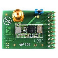
Dev Kit Accessory
Manufacturer
Semtech
Specifications of SM1211E915
Modulation Type
FSK, OOK
Data Rate Max
200Kbps
Frequency Range
902MHz To 928MHz
Supply Voltage Range
2.1V To 3.6V
Module Interface
SPI
Supply Current
25mA
Accessory Type
RF Module
Sensitivity
-105dBm
Operating Temperature (min)
-40C
Operating Temperature (max)
85C
Operating Temperature Classification
Industrial
Package Type
TQFN EP
Operating Supply Voltage (min)
2.1V
Operating Supply Voltage (typ)
2.5/3.3V
Operating Supply Voltage (max)
3.6V
Sensitivity (dbm)
-105dBm
Rohs Compliant
NA
Lead Free Status / RoHS Status
na
Lead Free Status / RoHS Status
na


With the recommended Bill Of Materials (BOM) of the reference design of section 7.5.3, the PLL prototype is the
following:
The integrated VCO requires only two external tank circuit inductors. As the input is differential, the two inductors
should have the same nominal value. The performance of these components is important for both the phase noise
and the power consumption of the PLL. It is recommended that a pair of high Q factor inductors is selected. These
should be mounted orthogonally to other inductors (in particular the PA choke) to reduce spurious coupling
between the PA and VCO. In addition, such measures may reduce radiated pulling effects and undesirable
transient behavior, thus minimizing spectral occupancy. Note that ensuring a symmetrical layout of the VCO
inductors will further improve PLL spectral purity.
For best performance wound type inductors, with tight tolerance, should be used as described in section 7.5.3.
To guarantee the optimum operation of the VCO over the SX1211’s frequency and temperature ranges, the
following settings should be programmed into the SX1211:
Table 10: MCParam_Freq_band Setting
To ensure that the frequency band of operation may be accurately addressed by the R, P and S dividers of the
synthesizer, it is necessary to ensure that the VCO is correctly centered. Note that for the reference design (see
section 7.5) no centering is necessary. However, any deviation from the reference design may require the
optimization procedure, outlined below, to be implemented. This procedure is simplified thanks to the built-in VCO
trimming feature which is controlled over the SPI interface. This tuning does not require any RF test equipment,
and can be achieved by simply measuring Vtune, the voltage between pins 6 (LFM) and 7 (LFP).
The VCO is centered if the voltage is within the range:
Note that this measurement should be conducted when in transmit mode at the center frequency of the desired
band (for example ~867 MHz in the 863-870 MHz band), with the appropriate MCParam_Freq_band setting.
If this inequality is not satisfied then adjust the MCParam_VCO_trim bits from 00 whilst monitoring Vtune. This
allows the VCO voltage to be trimmed in + 60 mV increments. Should the desired voltage range be inaccessible,
the voltage may be adjusted further by changing the tank circuit inductance value. Note that an increase in
inductance will result in an increase Vtune.
Rev 7 – Sept 2
ADVANCED COMMUNICATIONS & SENSING
Target channel
Freq_band
64 ≤ R ≤ 169
S < P+1
PLLBW = 15 kHz nominal
Startup times and reference frequency spurs as specified.
(MHz)
3.2.5. Voltage Controlled Oscillator
nd
, 2008
3.2.5.1. SW Settings of the VCO
3.2.5.2. Trimming the VCO Tank by Hardware and Software
863-
870
10
902-
915
00
915-
928
01
950-
960
10
50
Vtune
Page 15 of 92
(
mV
)
150
www.semtech.com
SX1211
Related parts for SM1211E915
Image
Part Number
Description
Manufacturer
Datasheet
Request
R

Part Number:
Description:
Ultra Low Power Integrated Uhf Transceiver Module
Manufacturer:
Semtech Corporation
Datasheet:


Part Number:
Description:
TVS 300W 12V SOT-23
Manufacturer:
Micro Commercial Components (MCC)
Datasheet:

Part Number:
Description:
EVALUATION BOARD
Manufacturer:
Semtech
Datasheet:
Part Number:
Description:
EVALUATION BOARD
Manufacturer:
Semtech
Datasheet:
Part Number:
Description:
VOLTAGE SUPPRESSOR, TRANSIENT SEMTECH
Manufacturer:
Semtech
Datasheet:
Part Number:
Description:
HIGH VOLTAGE CAPACITORS MONOLITHIC CERAMIC TYPE
Manufacturer:
Semtech Corporation
Datasheet:
Part Number:
Description:
EZ1084CM5.0 AMP POSITIVE VOLTAGE REGULATOR
Manufacturer:
Semtech Corporation
Datasheet:
Part Number:
Description:
3.0 AMP LOW DROPOUT POSITIVE VOLTAGE REGULATORS
Manufacturer:
Semtech Corporation
Datasheet:
Part Number:
Description:
Manufacturer:
Semtech Corporation
Datasheet:
Part Number:
Description:
RailClamp Low Capacitance TVS Diode Array
Manufacturer:
Semtech Corporation
Datasheet:
Part Number:
Description:
Manufacturer:
Semtech Corporation
Datasheet:
Part Number:
Description:
Manufacturer:
Semtech Corporation
Datasheet: