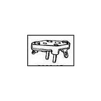
8080-1G7 Tyco Electronics, 8080-1G7 Datasheet - Page 46

8080-1G7
Manufacturer Part Number
8080-1G7
Description
TRANSISTOR SOCKET, 3POS, THROUGH HOLE
Manufacturer
Tyco Electronics
Datasheet
1.8080-1G7.pdf
(80 pages)
Specifications of 8080-1G7
Connector Type
TO-3 Socket
No. Of Contacts
3
Pitch Spacing
5.46mm
Contact Termination
Solder
Contact Material
Beryllium Copper
Contact Plating
Gold
Socket Mounting
PC Board
Lead Free Status / RoHS Status
Contains lead / RoHS non-compliant
5046
OVERVIEW
The AMP HOLTITE Socket contact is a solderless, zero-profile contact
designed to be contained within the barrel of a plated-thru hole.
The unique design allows the contact and the plated-thru hole to form a
zero-profile component socket which provides both the normal forces and
the low contact resistance required to mechanically retain and electrically
interconnect a broad range of electronic parts and components.
The outer shape of the HOLTITE Socket contact allows the plated-thru
hole to elastically conform during insertion. The precision machined
geometry allows for the controlled deformation of plated material without
damaging the plated-thru hole or affecting the normal electrical and
mechanical contact performance.
MATERIALS AND DESIGN
HOLTITE Socket contacts are precision machined from double-drawn
solid beryllium-copper wire, and then heat treated. Beryllium copper is
used because of its spring properties after heat treating. The copper affords
excellent conductivity, while the beryllium lends hardness and durability
to the finished contact.
The HOLTITE Socket contact has been machined as a seamless heat
treated part, which gives it more uniform and repeatable spring properties
than those of a stamped contact used in an identical through hole diameter.
This uniformity of normal forces minimizes variations in contact
resistance and is designed for the proper insertion/withdrawal forces on
mating parts.
The HOLTITE Socket contact has been designed to provide a solderless
gas tight electrical connection with mating parts. The angled contact
opening greatly facilitates lead entry (especially important when
automatically inserting IC’s), and reduces the possibility of lead or plating
damage. Two locking collars provide contact retention through a
controlled elastic deformation, and a machined groove between the collars
provides a relief for the compressive radial forces of the plated-thru hole
plating material. Concentration of the forces and elastic deformation in
this manner locks the contact in place.
A transition region below the lower collar serves as a relief area for any
plastic deformation of plating material that may occur as the contact is
inserted into the plated-thru hole. This relief provides the consistency of
contact normal forces over slight variations in hole size, because plated-
thru hole walls (under prescribed plating tolerances) will not come into
contact with the beam of the HOLTITE Socket fingers.
Products for Industrial &
Commercial Applications
Dimensions are shown for
reference purposes only.
Discrete Sockets
HOLTITE Socket Application Notes
Dimensions are in inches and
millimeters unless otherwise
specified. Values in brackets
are metric equivalents.
HOLE REQUIREMENTS
The fingers of 5P series HOLTITE Socket contacts will protrude out of
circuit boards that are less than 3/32" (2,38 mm) thick. Care in board
handling should be exercised in this case to prevent damage to the exposed
contact fingers. This is not a concern in board thicknesses of 3/32" or
greater because the contact fingers are entirely contained within the
plated-thru hole.
The press fit technology used for installing HOLTITE Socket contacts is
directly dependent on the hole size tolerance. The tolerances of the
primary and finished hole sizes in a printed circuit board must be
sufficiently narrow for adequate compressive stress between the hole walls
and the locking collars of the contact.
The primary (drilled) hole size is a very important dimension. Finished
hole tolerances should NOT be maintained by drilling over-sized holes
and then plating down to the correct size, because copper and tin/lead
alone will not create the compressive forces necessary to retain the
HOLTITE Socket contact over time and temperature ranges. Drilling
undersized holes, on the other hand, may introduce problems such as
excessive contact insertion forces, board warpage and crazing around the
hole. Holes should be drilled from the component insertion side of the
board, whenever possible, to avoid creating drill-exit burrs on the press-fit
portion of the thru-hole.
transition
groove
region
Specifications subject to
change.
Profile Cross-Section
Figure 4
entry
Technical Support Center
1-800-522-6752
www.tycoelectronics.com
Catalog 1307612
locking
collar
Revised 7-01


