2000905-1 Tyco Electronics, 2000905-1 Datasheet - Page 3
2000905-1
Manufacturer Part Number
2000905-1
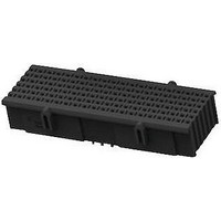
Description
BACKPLANE CONNECTOR, RECEPT, 180POS
Manufacturer
Tyco Electronics
Series
Fortis Zdr
Datasheet
1.2000895-1.pdf
(18 pages)
Specifications of 2000905-1
Row Pitch
1.6mm
Pitch Spacing
1.9mm
No. Of Contacts
180
Gender
Receptacle
Contact Termination
Press Fit
No. Of Rows
9
Contact Plating
Gold
Connector Type
Backplane
Product Type
Contact Modules
Contact Gender
Socket (Female)
Number Of Positions / Contacts
180
Mounting Style
PCB
Mounting Angle
Vertical
Lead Free Status / Rohs Status
Lead free / RoHS Compliant


The connector system consists of a vertical receptacle (motherboard) and a right- - angle header (daughter card)
consisting of a configuration of end modules, center modules, stand alone modules, double- - wide center
modules, and double- - wide stand alone modules. The stand alone modules have full shrouds. Each module
contains signal and ground eye- -of- - needle compliant pin (press- -fit) contacts.
The receptacle module has 10 (end and center) or 20 (double- -wide center) columns and 9 rows of contacts.
The header modules have 10 (left, right, and center) or 20 (double- -wide center) chicklets with each containing
9 contacts. Both are available in 2 or 3 pairs.
For initial alignment during mating, the chamfered lead- -in around the edges of the mating side of the header
modules captures and guides the mating side of the receptacle module. Alignment lugs and alignment slots are
molded onto the ends of the modules to provide blind mating. Universal and keyed guide hardware are
available for proper mating and allow up to +3.0 offset for blind mating. The guide hardware consists of a guide
pin and guide module. The connectors require 2 guide pins (for the receptacle) and 2 guide modules (for the
header) and must be attached to the pc board. Refer to Figure 2.
The modules can be seated on the pc board using manual application tooling.
The module profile size (pitch) is 25.4. The density, defined as a combination of the amount of columns and
contacts per module, is provided in Figure 3.
1.1. Contact Length
Length of the contacts is given in Figure 4.
Female
Guide Module
Rev B
Universal Guide Hardware
Double--Wide Center, Double--Wide Stand Alone
Mating Surface of Module
Guide Pin
End, Center, Stand Alone
MODULE TYPE
MODULE TYPE
Ground Contact
7.35
Female
Guide Module
Keyed Guide Hardware
COLUMNS
Keyed
Surface
Figure 2
Figure 4
Figure 3
10
20
Guide Pin
Contacts
120
2--PAIR MODULE
60
Signal Contact
Keyed
Surface
5.85
Differential
DENSITY
Pairs
20
40
Keyed VITA 46 Type Guide Hardware
Female
Guide Module
Contacts
180
3--PAIR MODULE
90
Differential
Guide Pin
Pairs
30
60
114- - 13267
3 of 18
Related parts for 2000905-1
Image
Part Number
Description
Manufacturer
Datasheet
Request
R

Part Number:
Description:
Battery Interconnection System for Portable Electronics; BU CONN FS6 8POS DIP TYPE ASSY ( AMP )
Manufacturer:
Tyco Electronics
Part Number:
Description:
Manufacturer:
Tyco Electronics
Datasheet:
Part Number:
Description:
Manufacturer:
Tyco Electronics
Datasheet:


