2000905-1 Tyco Electronics, 2000905-1 Datasheet - Page 9
2000905-1
Manufacturer Part Number
2000905-1
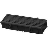
Description
BACKPLANE CONNECTOR, RECEPT, 180POS
Manufacturer
Tyco Electronics
Series
Fortis Zdr
Datasheet
1.2000895-1.pdf
(18 pages)
Specifications of 2000905-1
Row Pitch
1.6mm
Pitch Spacing
1.9mm
No. Of Contacts
180
Gender
Receptacle
Contact Termination
Press Fit
No. Of Rows
9
Contact Plating
Gold
Connector Type
Backplane
Product Type
Contact Modules
Contact Gender
Socket (Female)
Number Of Positions / Contacts
180
Mounting Style
PCB
Mounting Angle
Vertical
Lead Free Status / Rohs Status
Lead free / RoHS Compliant


3.6. Placement
3.7. Spacing
Rev B
CAUTION
NOTE
A. Modules
The module number one position must be aligned with the number one position board hole. When placing
modules on the pc board, make sure that the contacts are aligned and started into the matching holes
before seating the module onto the pc board.
The entire “eye” of each contact must be within the pc board hole. Depending on the thickness of the pc
board, the contact tails may or may not protrude from the pc board.
B. Guide Hardware
The interaction of the guide pin and guide module provide error- -free mating and prevents damage to the
housings and contacts. The guide hardware is recommended for multi- - connector, large and heavy
daughter card applications, and conditions where misalignment tolerances given in Paragraph 3.10 cannot
be met. See Figure 8.
Placement of the guide hardware onto the pc boards must be applied with tooling capable of supplying a
downward force between 222 and 667 N [50 and 150 lb- - force]. The guide hardware must be fully seated
on the pc board. A customer- - supplied screw must be used with the guide module.
A. Modules End- - to- - End
Care must be used to avoid interference between adjacent modules. The recommended minimum
distance between modules to ensure proper mating is provided in Figure 9.
When using these modules with other connectors or components, call PRODUCT INFORMATION at the
number at the bottom of page 1 for recommended spacing.
!
i
Daughter Card
Modules should be handled only by the housing to avoid deformation, contamination, or damage to the contacts.
The information provided is for manual placement of modules. If robotic equipment is used, other space allowances
will be required for the grippers.
Guide Module (Ref)
Figure 8
Guide Pin (Ref)
Backplane
114- - 13267
9 of 18
Related parts for 2000905-1
Image
Part Number
Description
Manufacturer
Datasheet
Request
R

Part Number:
Description:
Battery Interconnection System for Portable Electronics; BU CONN FS6 8POS DIP TYPE ASSY ( AMP )
Manufacturer:
Tyco Electronics
Part Number:
Description:
Manufacturer:
Tyco Electronics
Datasheet:
Part Number:
Description:
Manufacturer:
Tyco Electronics
Datasheet:


