LS037V7DW01 Sharp Microelectronics, LS037V7DW01 Datasheet
LS037V7DW01
Specifications of LS037V7DW01
Available stocks


Related parts for LS037V7DW01


LS037V7DW01 Summary of contents
Page 1
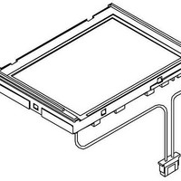
... Technical Document LCD Specification LCD Group LS037V7DW01 LCD Module Product Specification March 2008 Transflective LCD module with touch panel. Resolution is selectable between VGA (480H × 640V) or QVGA (240H × 320V). Color mode is selectable between 262,144 colors (18-bit RGB colors (3-bit RGB). ...
Page 2
...
Page 3
...
Page 4
This publication is the proprietary of SHARP and is copyrighted, with all rights reserved. Under the copyright laws, no part of this publication may be reproduced or transmitted in any form or by any means, electronic or mechanical for any ...
Page 5
... Application This literature applies to LS037V7DW01. (2) Overview This module is a color transflective and active matrix LCD module incorporating CG-Silicon TFT (Continuous Grain-Silicon Thin Film Transistor composed of a color TFT-LCD panel, driver ICs (with control Function), an FPC(with DC-DC Converter), a back light, a touch panel and a back sealed casing. ...
Page 6
Input/Output terminal 5-1) TFT-LCD panel and Backlight driving section Table2 Pin No. Symbol I/O 1 LED+ - - 3 LED- - 4 NC - - - - - 9 ...
Page 7
Pin No. Symbol I GND - GND - ...
Page 8
Selection for Vertical/ Horizontal synchronizing SMPSYNC signal timing(clock timing) High Rise edge of clock(CLKIN) Low Fall edge of clock(CLKIN) (6)Absolute Maximum Ratings Table 3 Parameter Power supply (COG driver / Digital) ...
Page 9
Cautions when you turn on or off the power supply CLKIN,VSYNC,HSYNC RGB data Signal RESB INI(Power on Control) VCC (External power Supply 3.3V) (1) After VCC is ON ,please make sure to start HVIF(CLK,HSYNC,VSYNC,RGB data signal) synchronized signal before ...
Page 10
Timing Characteristics of input signals Table 6 Parameter CLK Period CLK Low Width CLK High Width Data setup time Data hold time Pulse width of DEN Period of HSYNC Pulse width of HSYNC HSYNC setup time HSYNC hold time ...
Page 11
HSYNC Period(VGA:Typ.648CLK, QVGA:Typ.324CLK) 【Note 7-5】VSYNC,HSYNC,CLK,R0~R5,G0~G5,B0~B5,DEN terminals are applied. Input Signal 【Note 7-6】INI,RESB terminals are applied. Input Signal 【Note 7-7】Reset Signal Timing chart RESB 7-3)Power consumption Measurement condition : Vsync=59.94Hz,Hsync=38.84kHz,CLK=25.17MHz,Ta=25℃ (VGA Mode) Table 7 Parameter VSHD Total(Digital+Analog) 【Note ...
Page 12
VGA Mode Timing Chart] 【※1】 [Vertical Timing] t vsw VSYNC HSYNC 648 CLKIN RIN[5:0] GIN[5:0] 1LINE 2LINE BIN[5:0] [Horizontal Timing] t HSW HSYNC t HBP DEN CLK RIN[5:0] GIN[5:0] BIN[5:0] 【 1】 VSYS ...
Page 13
QVGA Mode Timing Chart] 【※1】 [Vertical Timing] t VSW VSYNC HSYNC 324 CLKIN RIN[5:0] GIN[5:0] 1LINE 2LINE BIN[5:0] [Horizontal Timing] HSYNC t HBP t HSW DEN CLK RIN[5:0] GIN[5:0] BIN[5:0] 【※1】 VSYS VSYH ...
Page 14
Input Signals, Basic Display Color and Gray Scale of Each Color Table 8 Colors & Gray scale R0 R1 Gray Scale Black 0 - Blue 0 - Green 0 - Cyan 0 - Red 1 - Magenta 1 - ...
Page 15
Not driving the Back light condition Table 9 Parameter Symbol Viewing angle θ21,22 range θ11, 12 Contrast ratio CRmax Response Rise time Fall White chromaticity Reflection ratio * The measuring method of the optical characteristics is shown ...
Page 16
Driving the Back light condition Table 10 Parameter Symbol θ21,22 Viewing angle range Contrast ratio Crmax Rise Response time Fall White chromaticity NTSC ratio Brightness Uniformity * The measuring method of the optical characteristics is shown by the following ...
Page 17
The contrast ratio is defined as follows: Photodetecter output with all pixels white(GS63) Contrast ratio(CR) = Photodetecter output with all pixels black(GS0) V =5.0Vp-p COMAC The response time is defined as the following figure and shall be measured by ...
Page 18
Uniformity Minimum Brightness Uniformity = Maximum Brightness The brightness should be measured on the 9-point as shown in the right figure. (10) Display quality The display quality of the color TFT-LCD module shall be in compliance with ...
Page 19
If an consumer will put a palm on housing in normal usage, care should be taken as follows. (2) Keep the gap, for example 0.3 to 0.7mm,between bezel edge and T/P surface. The reason is ...
Page 20
Precautions 14-1) Insertion and taking out of FPCs (1) Be sure insert and take out of the FPC into the connector of the set after turning off the power supply on the set side. 14-2) Handling of FPCs (1) ...
Page 21
Test Conditions for TFT-LCD Module Table 12 No. Test items 1 High temperature storage test 2 Low temperature storage test 3 High temperature and high humidity operating test 4 High temperature operating test 5 Low temperature operating test 6 ...
Page 22
Ambient temperature Panel temperature 【Check items】 ・Test No.1~9 In the standard condition, there shall be no practical problems that may affect the display function. ・Test No.10~No.11 The measurements after the tests are satisfied (11)-Table 11 (Touch ...
Page 23
...
Page 24
...
Page 25
... Technical Document LCD Specification LCD Group NORTH AMERICA Sharp Microelectronics of the Americas 5700 NW Pacific Rim Blvd. Camas, WA 98607, U.S.A. Phone: (1) 360-834-2500 Fax: (1) 360-834-8903 www.sharpsma.com TAIWAN Sharp Electronic Components (Taiwan) Corporation 8F-A, No. 16, Sec. 4, Nanking E. Rd. Taipei, Taiwan, Republic of China Phone: (886) 2-2577-7341 ...