LQ035Q7DH07 Sharp Microelectronics, LQ035Q7DH07 Datasheet
LQ035Q7DH07
Specifications of LQ035Q7DH07


Related parts for LQ035Q7DH07


LQ035Q7DH07 Summary of contents
Page 1
... P S RODUCT PECIFICATIONS LQ035Q7DH07 TFT-LCD Module Spec. Issue Date: May 15, 2006 AVC Liquid Crystal Displays Group No: LCP-06012 ...
Page 2
...
Page 3
... RECORDS OF REVISION MODEL No.:LQ035Q7DH07 SPEC No.:LCP-06012 NO. 2006.05.15 LCP-06012 PAGE SUMMARY - - NOTE 1st Issue ...
Page 4
This publication is the proprietary of SHARP and is copyrighted, with all rights reserved. Under the copyright laws, no part of this publication may be reproduced or transmitted in any form or by any means, electronic or mechanical for any ...
Page 5
... Application This specification applies to LQ035Q7DH07 (2) Overview This module is a color active matrix LCD module incorporating amorphous silicon TFT (Thin Film Transistor), named AD-TFT (Advanced TFT practicable in both transmissive-type and reflection-type modes composed of a color TFT-LCD panel, driver ICs, an FPC, a back light, and a back sealed casing. It isn’t composed control circuit. Graphics and texts can be displayed on a 240× ...
Page 6
Input/Output terminal 5-1) TFT-LCD panel driving section Recommendation CN:HIROSE FH12A-50S-0.5SH(55) or FH12-50S-0.5SH(55) Table2 Pin No. Symbol I/O VL1 I Power supply for LED (High voltage VL2 I Power supply for LED (Low voltage ...
Page 7
Pin No. Symbol I/O 40 DGND - Ground(digital RED data signal(MSB RED data signal RED data signal RED data signal RED data signal 46 R0 ...
Page 8
Maximum Ratings Parameter Power supply(source/Analog) Power supply(source/Digital) Power supply (gate) Power supply (gate) Input voltage (Digital) Operating temperature (panel surface) Storage temperature [Terminal A] MOD,U/L,SPS,CLS,SPL,R0 to R5,G0 to G5,B0 to B5,LP,DCLK,LBR,SPR,PS,REV 【Note6】Humidity: 95%RH Max.(at Ta ≤ 40˚C). Maximum wet-bulb ...
Page 9
Recommended operating conditions A) TFT-LCD panel driving section Table 4 Parameter Supply voltage for source driver (Analog) Supply voltage for source driver (Digital) Supply voltage High voltage for gate driver Low voltage Input voltage for Source driver ...
Page 10
B) Back light driving section Table 5 Parameter LED voltage LED current Power consumption 【Note 7-6】Calculated reference value(I 7-2) Timing Characteristics of input signals Table 6 AC Characteristics (1) Parameter Clock frequency of source driver Rising time of clock Falling ...
Page 11
DCLK 20% T wlp LP T susp T sulp SPL T wsp hcls CLS T sups PS VCOM 80% 80 20% T cwl ...
Page 12
T rcls T whcls T wlcls 80% CLS 1 20% 20% 20% T susps T hsps 80% SPS 20% 20% T fsps T rsps Non-display period fcls 80% ...
Page 13
Power consumption Measurement condition: SPS=60Hz, CLS=15.73kHz, SPL=15.73kHz, DCLK=6.3MHz The term of PS=”Lo” in one horizontal period … 37μsec (234DCLK) Ta=25˚C Table 7 Parameter Sym Source Analog I current Digital I Gate High I current Low I Conditions Min. - ...
Page 14
Signals, Basic Display Color and Gray Scale of Each Color Table 8 Colors & Gray scale Gray Scale R0 R1 Black - 0 0 Blue - 0 0 Green - 0 0 Cyan - 0 0 Red - 1 ...
Page 15
Back light condition Table 9 Parameter Symbol θ21,22 θ11 Viewing angle range θ12 Contrast ratio CRmax τ r Response Rise τ d time Fall x White chromaticity y x Red chromaticity y x Green chromaticity ...
Page 16
Back light condition Table 10 Parameter Symbol θ21,22 θ11 Viewing angle range θ12 Contrast ratio Crmax τr Response Rise τd time Fall x White chromaticity y x Red chromaticity y x Green chromaticity y x Blue chromaticity y ...
Page 17
Viewing angle range is defined as follows. 6o’clock direction [Note 9-2] Definition of contrast ratio: The contrast ratio is defined as follows: Contrast ratio (CR) V [Note 9-3] Definition of response time: The response time is defined as ...
Page 18
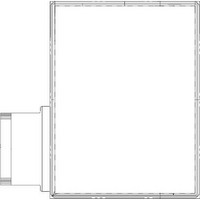
Display quality The display quality of the color TFT-LCD module shall be in compliance with the Incoming Inspection Standards for TFT-LCD. (11) Mechanical characteristics 11-1) External appearance See Fig. 1 11-2) FPC (for LCD panel) characteristics (1)Specific connector FH12A-50S-0.5SH(55) ...
Page 19
... Others 14-1) Indication of lot number The lot number is shown on a label. Attached location is shown in Fig.1 (Outline Dimensions). LQ035Q7DH07 ○○○○○○○○○○ model No. 14-2) Used Regulation of Chemical Substances Breaking Ozone Stratum Substances with the object of regulating: CFCS, Carbon tetrachloride, Halon 1,1,1-Trichloro ethane (Methyl chloroform) (a) This LCD module, Constructed part and Parts don’ ...
Page 20
Forwarding form (See Fig.2 Package Form) a) Piling number of cartons : Max 8 b) Package quality in one cartons : 100pcs c) Carton size : 575mm × 332mm × 209mm d) Total mass of 1 carton filled with ...
Page 21
LCP-06012-18 ...
Page 22
Fig.2 Forwarding form LCP-06012-19 ...
Page 23
... ALL EXPRESS AND IMPLIED WARRANTIES, INCLUDING THE WARRANTIES OF MERCHANTABILITY, FITNESS FOR USE AND FITNESS FOR A PARTICULAR PURPOSE, ARE SPECIFICALLY EXCLUDED event will SHARP be liable any way responsible, for any incidental or consequential economic or property damage. NORTH AMERICA SHARP Microelectronics of the Americas 5700 NW Pacific Rim Blvd. Camas, WA 98607, U.S.A. Phone: (1) 360-834-2500 ...