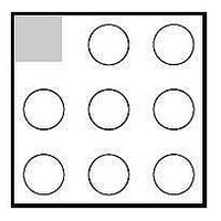
IP4064CX8/LF,135 NXP Semiconductors, IP4064CX8/LF,135 Datasheet - Page 3

IP4064CX8/LF,135
Manufacturer Part Number
IP4064CX8/LF,135
Description
ESD Suppressors INTEGRATED ESD
Manufacturer
NXP Semiconductors
Specifications of IP4064CX8/LF,135
Mounting Style
Surface Mount
Termination
Flat Style
Product Height (mm)
0.7mm
Operating Voltage
5.5 V
Channels
3 Channels
Breakdown Voltage
6 V to 10 V
Capacitance
20 pF
Termination Style
SMD/SMT
Package / Case
WLCSP-8
Power Dissipation Pd
180 mW
Operating Temperature Range
- 30 C to + 85 C
Lead Free Status / RoHS Status
Compliant
Other names
/T3 934058497135 IP4064CX8/LF
NXP Semiconductors
4. Functional diagram
5. Limiting values
IP4064CX8LF_IP4364CX8LF_1
Product data sheet
Table 3.
In accordance with the Absolute Maximum Rating System (IEC 60134).
[1]
Symbol
V
V
P
P
T
T
T
Fig 3. Schematic diagram IP4064CX8/LF and IP4364CX8/LF
stg
reflow(peak)
amb
I
ESD
ch
tot
Device is tested with 1000 pulses of 15 kV contact discharges each, according the IEC61000-4-2 model
and so exceeds the specified level 4 (8 kV contact discharge) by far.
Limiting values
Parameter
input voltage
electrostatic discharge
channel power dissipation
total power dissipation
storage temperature
peak reflow temperature
ambient temperature
protection pins
IEC61000-4-2
Rev. 01 — 12 November 2007
level 1
Integrated SIM card passive filter array with ESD protection
C3
A3
B3
IP4064CX8/LF; IP4364CX8/LF
Conditions
pins A2, B1, C1, C2 to B2
IEC 61000-4-2, Level 4,
pins A2, B1, C1, C2 to B2
IEC 61000-4-2, Level 1, all
other pins to B2
continuous power;
T
T
10 s maximum
amb
amb
contact discharge
air discharge
contact discharge
air discharge
contact discharge and air
discharge
100
100
47
B2
R1
R2
R3
= 70 C
= 70 C
IEC61000-4-2
level 4
protection pins
C2
A2
B1
C1
001aag217
[1]
[1]
Min
-
-
-
0.5
15
15
8
15
2
55
30
© NXP B.V. 2007. All rights reserved.
Max
+5.5
+15
+15
+8
+15
+2
60
180
+150
260
+85
Unit
V
kV
kV
kV
kV
kV
mW
mW
3 of 13
C
C
C


