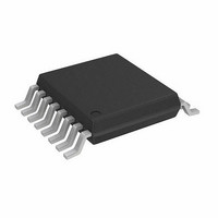
A4934GLPTR-T Allegro Microsystems Inc, A4934GLPTR-T Datasheet - Page 4

A4934GLPTR-T
Manufacturer Part Number
A4934GLPTR-T
Description
IC BLDC DVR 3PHASE 16-ETSSOP
Manufacturer
Allegro Microsystems Inc
Datasheet
1.A4934GLPTR-T.pdf
(8 pages)
Specifications of A4934GLPTR-T
Applications
Fan Motor Driver, 3-Phase
Number Of Outputs
1
Current - Output
500mA
Voltage - Supply
8 V ~ 16 V
Operating Temperature
-40°C ~ 105°C
Mounting Type
Surface Mount
Package / Case
16-TSSOP (0.173", 4.40mm Width) Exposed pad
Lead Free Status / RoHS Status
Lead free / RoHS Compliant
Voltage - Load
-
Lead Free Status / RoHS Status
Supplier Unconfirmed, Lead free / RoHS Compliant
Other names
620-1382-2
A4934
The driver system is a three-phase, BEMF sensing motor control-
ler and driver. Commutation is controlled by a proprietary BEMF
sensing technique.
The motor drive system consists of three half bridge NMOS
outputs, BEMF sensing circuits, adaptive commutation control,
and state sequencer. The sequencer determines which output
devices are active. The BEMF sensing circuits and adaptive com-
mutation circuits determine when the state sequencer advances to
the next state.
A complete self-contained BEMF sensing commutation scheme is
provided. The three half-bridge outputs are controlled by a state
machine with six possible states, shown in figure 1. Motor BEMF
is sensed at the tri-stated output for each state.
BEMF sensing motor commutation relies on the accurate com-
parison of the voltage on the tri-stated output to the voltage at the
center tap of the motor. The BEMF zero crossing, the point where
the tri-stated motor winding voltage crosses the center tap volt-
age, is used as a positional reference. The zero crossing occurs
roughly halfway through one commutation cycle.
CDCOM
Figure 1. Motor Terminal Output States
Output
FCOM
OUTB
OUTC
OUTA
State
FG
A
B
Functional Description
C
D
E
Three-Phase Sensorless Fan Driver
F
Adaptive commutation circuitry and programmable timers
determine the optimal commutation points with minimal
external components. The major blocks within this system are:
the BEMF zero crossing detector, Commutation Delay timer, and
the Blank timer.
BEMF Zero Cross Detection
BEMF zero crossings are detected by comparing the voltage at
the tri-stated motor winding to the voltage at the motor center
tap. Zero crossings are indicated by the FCOM signal, which
goes high at each valid zero crossing and low at the beginning
of the next commutation. In each state, the BEMF detector looks
for the first correct polarity zero crossing and latches it until the
next state. This latching action, along with precise comparator
hysteresis, makes for a robust sensing system. At the beginning
of each commutation event, the BEMF detectors are inhibited for
a period of time set by the Blank timer. This is done so that com-
mutation transients do not disturb the BEMF sensing system.
Commutation Event
See figure 1 for timing relationships. The commutation sequence
is started by a CDCOM pulse or a valid XCOM at startup. After
A
B
C
D
E
F
115 Northeast Cutoff
1.508.853.5000; www.allegromicro.com
Allegro MicroSystems, Inc.
Worcester, Massachusetts 01615-0036 U.S.A.
4


