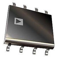
IR1153SPBF International Rectifier, IR1153SPBF Datasheet - Page 3

IR1153SPBF
Manufacturer Part Number
IR1153SPBF
Description
IC PFC ONE CYCLE CONTROL 8SOIC
Manufacturer
International Rectifier
Datasheet
1.IR1153STRPBF.pdf
(20 pages)
Specifications of IR1153SPBF
Mode
Continuous Conduction (CCM)
Frequency - Switching
18.3kHz ~ 25kHz
Current - Startup
26µA
Voltage - Supply
14 V ~ 17 V
Operating Temperature
-25°C ~ 125°C
Mounting Type
*
Package / Case
*
Startup Current
26µA
Operating Supply Current
7mA
Duty Cycle (%)
99%
Frequency
22.2kHz
Digital Ic Case Style
SOIC
No. Of Pins
8
Operating Temperature Range
-25°C To +125°C
Peak Reflow Compatible (260 C)
Yes
Rohs Compliant
Yes
Supply Voltage Range
14V To 17V
Package
8-lead SOIC
Circuit
PFC IC
Vcc Range (v)
14V-17V
Out Peak Current (a)
+/- 0.75
Switching Frequency (khz)
22.2
Environment
Industrial
Over-voltage Protection
Yes
Brown-out Protection
Yes
Pbf
Yes
Lead Free Status / RoHS Status
Lead free / RoHS Compliant
www.irf.com
The electrical characteristics involve the spread of values guaranteed within the specified supply voltage and
related to 25°C. If not otherwise stated, a supply voltage of V
junction temperature range T
Electrical Characteristics
Supply Section
Supply Voltage Operating
Range
V
V
(Under Voltage Lock Out)
V
Operating Current
Start-up Current
Sleep current
Sleep Mode Threshold
Oscillator Section
Fixed Oscillator Frequency
Maximum Duty Cycle
Minimum Duty Cycle
Protection Section
Open Loop Protection
(OLP)Threshold
Output Overvoltage
Protection (OVP)
Threshold
Output Overvoltage
Protection Reset Threshold
OVP Input Bias Current
Brown-out Protection
(BOP) Threshold
Brown-out Protection
Enable Threshold
BOP Input Bias Current
Peak Current Limit
Protection ISNS Voltage
Threshold (IPK LIMIT)
CC
CC
CC
Turn On Threshold
Turn Off Threshold
Turn On/Off Hysteresis
Parameters
Parameters
Parameters
J
from – 25° C to 125°C. Typical values represent the median values, which are
V
V
V
I
Symbol
V
I
V
I
Symbol
Symbol
CC START
V
V
OVP(Bias)
BOP(Bias)
OVP(RST)
I
CC UVLO
CC HYST
ISNS(PK)
D
V
V
BOP(EN)
D
V
SLEEP
V
CC ON
SLEEP
f
I
SW
CC
MAX
OLP
OVP
BOP
MIN
CC
-0.58
12.2
20.2
18.3
Min.
0.66
1.46
Min.
Min.
104
101
9.4
2.4
0.5
93
17
-0.51
13.1
Typ.
Typ.
10.1
Typ.
22.2
0.76
1.56
106
103
3.5
14
26
26
19
3
3
-0.44
Max.
Max.
10.8
Max.
24.2
0.86
1.66
-0.2
-0.2
108
105
3.6
0.8
17
14
75
75
25
99
21
7
8
5
0
CC
=15V is assumed for test condition.
Units
Units
Units
V
V
V
kHz
mA
mA
mA
µA
µA
µA
µA
%
%
%
%
%
V
V
V
V
V
REF
REF
REF
V
V
V
C
C
OVP Mode, Inactive gate
V
Pin OVP/EN=V
Bias on OVP/EN pin
T
V
Pulse Skipping
Bias on VFB pin
Bias on OVP/EN pin
Bias on OVP/EN pin
Bias on BOP pin
Bias on BOP pin
Bias on ISNS pin
-25°C < T
AMB
CC
COMP
LOAD
LOAD
=V
=25°C
=5V
=1nF
=4.7nF
CC ON
AMB
© 2011 International Rectifier
- 0.2V
Remarks
Remarks
Remarks
< 125°C
SLEEP
IR1153S
-0.2V


