LPC2478-STK-MICTOR Olimex Ltd., LPC2478-STK-MICTOR Datasheet
LPC2478-STK-MICTOR
Specifications of LPC2478-STK-MICTOR
Available stocks


Related parts for LPC2478-STK-MICTOR


LPC2478-STK-MICTOR Summary of contents
Page 1
LPC-2478STK development board Copyright(c) 2009, OLIMEX Ltd, All rights reserved Users Manual Rev. B November 2009 Page 1 ...
Page 2
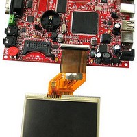
... INTRODUCTION: LPC-2478STK is a starter kit which uses MCU LPC2478 from NXP. This powerful MCU supports various serial interfaces such as USB host, USB device, UART, CAN, etc. In addition you will find also audio input and output as well as MP3 decoder, digital accelerometer, JTAG, Ethernet, touchscreen TFT display and SD/MMC card connector on this board. All this along with the ARM7TDMI-S™ ...
Page 3
... Hardware: Programmer/Debugger – ARM-JTAG, ARM-USB-TINY or ARM- Software: PROCESSOR FEATURES: LPC-2478STK board use MCU LPC2478 from NXP with these features: ARM7TDMI-S processor, running MHz. 512 kB on-chip flash program memory with In-System Programming (ISP) and In-Application Programming (IAP) capabilities. Flash program memory is on the ARM local bus for high performance CPU access ...
Page 4
USB 2.0 full-speed dual-port device/host/OTG controller with on-chip PHY and associated DMA controller. - Four UARTs with fractional baud rate generation, one with modem control I/O, one with IrDA support, all with FIFO. - CAN controller with two channels. ...
Page 5
On-chip power-on reset. On-chip crystal oscillator with an operating range of 1 MHz to 24 MHz. On-chip PLL allows CPU operation up to the maximum CPU rate without the need for a high frequency crystal. May be run from the ...
Page 6
Page 6 ...
Page 7
MEMORY MAP: Page 7 ...
Page 8
SCHEMATIC: -10V_E 2 1 220uF/10V/tnant 1.1K/1% 1N5819S VCC 1 10u/6.3V 2 C39 1 2 10u/6.3V C46 10u/6.3V C47 + CAN1_T 2 1 10u/6.3V C/SC USB USB 10u/6.3V + C60 C25 8.2k/1% R66 R65 6 ...
Page 9
... LPC-2478STK reset circuit is made with R68(47k) pull-up, capacitor C20(100nF) and the RST button. CLOCK CIRCUIT: Quartz crystal 12 MHz is connected to LPC2478 pin 44 (XTAL1) and pin 46 (XTAL2). Quartz crystal 32.768 kHz is connected to LPC2478 pin 34 (RTX1) and pin 36 (RTX2) and supplies the internal Real Time Clock. ...
Page 10
JUMPER DESCRIPTION: CAN_D disabled. Default state is open. CAN_T means that if you have only the jumpers of both devices should be If you have more than two devices, only the two end- devices should be closed. -10V_E the on ...
Page 11
... LPC2478 to the TFT display open, pin 162 of the LCP2478 is connected to EXT-7. Default state is closed. This jumper, when closed, outputs the LCD[16] signal from the LPC2478 to the TFT display open, pin 160 of the LCP2478 is connected to EXT-8. Default state is closed. This jumper, when closed, outputs the LCD[17] signal from the LPC2478 to the TFT display ...
Page 12
... This jumper controls the PHY signal of the Ethernet controller. If there is no jumper, the PHY is always enabled. If 1-2 are shorted, the PHY is disabled If 2-3 are shorted, the PHY is controlled by the LPC2478 signal Default state is no jumper (opened). EXT/JLINK This jumper controls the JLINK +5V power line (pin19) of ...
Page 13
... EXT/BAT This jumper controls the VBAT signal of the LPC2478. If 1-2 are shorted, the VBAT pin is supplied by an external battery. If 2-3 are shorted, the VBAT pin is supplied by the common board. Default state is 2-3 shorted. Page 13 +3.3VDC power supply for the ...
Page 14
... SD/MMC LED (red) with name SD connected to SD/MMC pin 4. Power-on LED (red) with name PWR – this LED shows that +3.3V is applied to the board. USB host LED (yellow) with name USB_H_LINK – connected to LPC2478 pin 147 (P1[13]/ENET_RX_DV). USB device LED (yellow) with name USB_D_LINK – connected to LPC2478 pin 66 (P1[18]/USB_UP_LED1/PWM1[1]/CAP1[0]) ...
Page 15
EXTERNAL CONNECTORS DESCRIPTION: JTAG: Pin # 1 +3.3V 3 TRSTN 5 TDI 7 TMS 9 TCK 11 RTCK 13 TDO 15 RST 17 GND 19 +5V_JLINK TDI Input Test Data In. This is the serial data input for the shift ...
Page 16
... RST Input Reset. When you use external software to program the LPC2478, this software uses the RS232 to connect to the device and if the jumper RST_E is put, than through this RST pin the software controls the #RESET pin of the MCU. (This pin is output for the RS232 and input for the LPC2478) ISP_E Input In-System Programming ...
Page 17
CANL and CANH are either deferential input, or differential output depending on the function of the MCP2551 CAN controller (receiving or transmitting data). Page 17 ...
Page 18
PWR: Pin # 1 Power Input 2 GND The power input should be +(9-12VDC)/6VAC. Audio In: Pin # GND 3 MCP MCP Input Microphone Input. This pin is input to the DSP codec VS1002D. Audio Out: Pin ...
Page 19
EXT: Pin # 1 GND 3 +5V 5 P0[5]/I2SRX_WS/LC D[1]/TD2/CAP2[1] 7 P0[7]/I2STX_CLK/LC D[9]/SCK1/MAT2[1] 9 P0[9]/I2STX_SDA/LC D[17]/MOSI1/MAT2[3] 11 RXD3 13 P4[30]/#CS0 15 P4[26]/BLS0 17 P4[17]/A17 19 P0[11]/RXD2/SCL2/M AT3[1] Signal Name Pin # ...
Page 20
UEXT: Pin # 1 +3.3V 2 GND 3 TXD2 4 RXD2 5 SCL2 6 SDA2 7 MISO 8 MOSI 9 SCK 10 SSEL USB host: Pin # 1 USB_PWRD2 2 U2D- 3 U2D+ 4 GND USB_PWRD2 Output USB Power. This ...
Page 21
U1D-, U1D+ depending on the direction of the data transfer. LAN: Pin # Signal Name Chip Side 1 TD+ 2 TD- 3 2.5V 4 LEDACT LED Color Right Yellow Left Green TD- OutputDifferential signal output. This signal is output from ...
Page 22
SD/MMC card slot: Pin # 1 MCIDAT3 3 GND (VSS1) 5 MCICLK 7 MCIDAT0 9 MCIDAT2 GND MCIDAT0-3 lines for the SD/MMC connector. They could be both input and output for the MCU depending on ...
Page 23
PS2: Pin # 1 KBO_IO GND 4 +5V 5 KBO_CLK 6 NC KBO_IO the keyboard and the MCU. KBO_CLK between the keyboard and the MCU. IrDA (optional chip): Pin # 1 +3. GND/TXD3 – ...
Page 24
MICTOR TRACE (optional): The MICTOR TRACE connector allows you to trace the execution of the programs. Page 24 ...
Page 25
MECHANICAL DIMENSIONS: All measures are in inches. Page 25 ...
Page 26
AVAILABLE DEMO SOFTWARE : LPC-2478STK is delivered pre-loaded with C Linux and the sources and binaries are on the accompanying CD. Page 26 ...
Page 27
ORDER CODE: LPC-2478STK – assembled and tested (no kit, no soldering required) How to order? You can order to us directly or by any of our distributors. Check our web All boards produced by Olimex are RoHS compliant Revision history: ...
Page 28
... OLIMEX in good faith. However all warranties implied or expressed including but not limited to implied warranties of merchantability or fitness for purpose are excluded. This document is intended only to assist the reader in the use of the product. OLIMEX Ltd. shall not be liable for any loss or damage arising from the use of any information in this document or any error or omission in such information or any incorrect use of the product ...