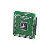
MA160014 Microchip Technology, MA160014 Datasheet - Page 123

MA160014
Manufacturer Part Number
MA160014
Description
MOD PLUG-IN 44PIN PIC18LF45K22
Manufacturer
Microchip Technology
Series
PIC® XLP™ 18Fr
Datasheet
1.PIC18F26J13-ISS.pdf
(496 pages)
Specifications of MA160014
Accessory Type
Plug-In Module (PIM) - PIC18LF45K10
Product
Microcontroller Modules
Data Bus Width
8 bit
Core Processor
PIC18LF45K22
Interface Type
I2C, SPI
Operating Supply Voltage
1.8 V to 5.5 V
Lead Free Status / RoHS Status
Lead free / RoHS Compliant
For Use With/related Products
PICDEM PIC18 Explorer, DM183032
Lead Free Status / Rohs Status
Lead free / RoHS Compliant
Available stocks
Company
Part Number
Manufacturer
Quantity
Price
Company:
Part Number:
MA160014
Manufacturer:
Microchip Technology
Quantity:
135
Company:
Part Number:
MA160014
Manufacturer:
MICROCHIP
Quantity:
12 000
- Current page: 123 of 496
- Download datasheet (5Mb)
9.6
The PIE registers contain the individual enable bits for
the peripheral interrupts. Due to the number of
peripheral interrupt sources, there are five Peripheral
Interrupt Enable registers (PIE1, PIE2, PIE3, PIE4 and
PIE5). When IPEN = 0, the PEIE/GIEL bit must be set to
enable any of these peripheral interrupts.
REGISTER 9-9:
2010 Microchip Technology Inc.
bit 7
Legend:
R = Readable bit
-n = Value at POR
bit 7
bit 6
bit 5
bit 4
bit 3
bit 2
bit 1
bit 0
U-0
—
PIE Registers
Unimplemented: Read as ‘0’.
ADIE: A/D Converter Interrupt Enable bit
1 = Enables the A/D interrupt
0 = Disables the A/D interrupt
RC1IE: EUSART1 Receive Interrupt Enable bit
1 = Enables the EUSART1 receive interrupt
0 = Disables the EUSART1 receive interrupt
TX1IE: EUSART1 Transmit Interrupt Enable bit
1 = Enables the EUSART1 transmit interrupt
0 = Disables the EUSART1 transmit interrupt
SSP1IE: Master Synchronous Serial Port 1 Interrupt Enable bit
1 = Enables the MSSP1 interrupt
0 = Disables the MSSP1 interrupt
CCP1IE: CCP1 Interrupt Enable bit
1 = Enables the CCP1 interrupt
0 = Disables the CCP1 interrupt
TMR2IE: TMR2 to PR2 Match Interrupt Enable bit
1 = Enables the TMR2 to PR2 match interrupt
0 = Disables the TMR2 to PR2 match interrupt
TMR1IE: TMR1 Overflow Interrupt Enable bit
1 = Enables the TMR1 overflow interrupt
0 = Disables the TMR1 overflow interrupt
R/W-0
ADIE
PIE1: PERIPHERAL INTERRUPT ENABLE (FLAG) REGISTER 1
W = Writable bit
‘1’ = Bit is set
RC1IE
R/W-0
R/W-0
TX1IE
Preliminary
U = Unimplemented bit, read as ‘0’
‘0’ = Bit is cleared
SSP1IE
R/W-0
PIC18(L)F2X/4XK22
CCP1IE
R/W-0
x = Bit is unknown
TMR2IE
R/W-0
DS41412D-page 123
TMR1IE
R/W-0
bit 0
Related parts for MA160014
Image
Part Number
Description
Manufacturer
Datasheet
Request
R

Part Number:
Description:
Manufacturer:
Microchip Technology Inc.
Datasheet:

Part Number:
Description:
Manufacturer:
Microchip Technology Inc.
Datasheet:

Part Number:
Description:
Manufacturer:
Microchip Technology Inc.
Datasheet:

Part Number:
Description:
Manufacturer:
Microchip Technology Inc.
Datasheet:

Part Number:
Description:
Manufacturer:
Microchip Technology Inc.
Datasheet:

Part Number:
Description:
Manufacturer:
Microchip Technology Inc.
Datasheet:

Part Number:
Description:
Manufacturer:
Microchip Technology Inc.
Datasheet:

Part Number:
Description:
Manufacturer:
Microchip Technology Inc.
Datasheet:


