V23993-EVA1035-H VINCOTECH, V23993-EVA1035-H Datasheet - Page 5
V23993-EVA1035-H
Manufacturer Part Number
V23993-EVA1035-H
Description
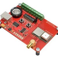
GPS Modules & Development Tools A1035-H GPS Eval Kit
Manufacturer
VINCOTECH
Type
Evaluation Boardr
Datasheet
1.V23993-EVA1035-H.pdf
(18 pages)
Specifications of V23993-EVA1035-H
Processor Used
SiRFStar III
Operating Voltage
3.3 V to 3.6 V
Interface Type
USB
Lead Free Status / RoHS Status
Lead free / RoHS Compliant
Lead Free Status / RoHS Status
Lead free / RoHS Compliant


V1.0 – Feb-09
1 Introduction
1.1 Purpose
The GPS Evaluation Kit EVA1035-H allows an easy evaluation of Vincotech’s GPS
receiver /smart antenna module A1035-H by offering quick access to the ports of
the module.
The EVA1035-H serves three major purposes:
• As a demonstration package of the module’s capabilities
• As an example how to integrate the module into a system
• To support an easy temporary design in
The EVA1035-H can especially demonstrate that the on-module GPS antenna and
an external active GPS antenna connected to the External Antenna input will result
in outstanding GPS performance. The user can switch between the two antennas
with the ANT_SW signal provided by the DIP switch.
A Supercap is used to continue RTC operation and to back-up SRAM during power
off periods. The firmware provided on the A1035-H delivered with the EVA1035-H is
identical to the standard firmware delivered on single A1035-H GPS receiver mod-
ules.
1.2 Contents
The EVA1035-H includes the following components:
Please check your package for completeness and connect the components prop-
erly.
Powering the A1035-H GPS receiver module via the USB connector with suffi-
cient view to the sky (or using an external active antenna with sufficient view to
the sky) will result in an NMEA output with position information.
The schematic in chapter “10 Board Schematics” is a basic example of how to
integrate the GPS module into an application or system.
The signals provided on the Evaluation Kit allow direct integration into a sur-
rounding system making it an ideal development tool.
• Demonstration board (labeled EVA1035-H) with one A1035-H GPS receiver /
• USB cable to connect to your PC
• CD with complete documentation and Vincotech’s GPS Cockpit software
smart antenna
User’s Manual
Page 5 of 18
Related parts for V23993-EVA1035-H
Image
Part Number
Description
Manufacturer
Datasheet
Request
R

Part Number:
Description:
GPS Modules & Development Tools GPS Demo/Eval kit for A1037-A Module
Manufacturer:
VINCOTECH
Part Number:
Description:
GPS Modules & Development Tools GPS Demo Kit for A1035-C Module
Manufacturer:
VINCOTECH
Datasheet:
Part Number:
Description:
GPS Modules & Development Tools USB DEMO KIT
Manufacturer:
VINCOTECH
Part Number:
Description:
GPS Modules & Development Tools GPS Receiver Module Full NMEA (SMD)
Manufacturer:
VINCOTECH
Datasheet:

Part Number:
Description:
GPS Modules & Development Tools A2100-A SiRFStarIV GPS Eval Kit
Manufacturer:
VINCOTECH

Part Number:
Description:
GPS Modules & Development Tools A2100-A SiRFStarIV GPS recvr mod (3.3V)
Manufacturer:
VINCOTECH

Part Number:
Description:
GPS Modules & Development Tools A1082A SiRF GSCi5000 Receiver module
Manufacturer:
VINCOTECH
Datasheet:
Part Number:
Description:
GPS Modules & Development Tools GPS Demo/Eval kit for A1080-A Module
Manufacturer:
VINCOTECH
Datasheet:

Part Number:
Description:
GPS Modules & Development Tools A1084-B GPS Eval Kit
Manufacturer:
VINCOTECH
Datasheet:
Part Number:
Description:
GPS Modules & Development Tools GPS Receiver Module with TXCO (SMD)
Manufacturer:
VINCOTECH
Datasheet:
Part Number:
Description:
GPS Modules & Development Tools GPS Demo Kit for A1029-D Module
Manufacturer:
VINCOTECH
Part Number:
Description:
GPS Modules & Development Tools GPS Receiver Module w/Smart Antenna
Manufacturer:
VINCOTECH
Part Number:
Description:
GPS Modules & Development Tools GPS Receiver Module Full NMEA Ext Temp
Manufacturer:
VINCOTECH
Datasheet:
Part Number:
Description:
GPS Modules & Development Tools GPS Demo Kit (USB) for A1029-C Module
Manufacturer:
VINCOTECH
Part Number:
Description:
Standard Power Integrated Module
Manufacturer:
Vincotech
Datasheet: